
Omnidirectional Vehicle Camera System

a vehicle camera and omnidirectional technology, applied in the field of video recording devices, can solve the problems of inability to accurately record the events of users, disadvantages, and users' inability to always know exactly, and achieve the effect of preparing fabricated events

Inactive Publication Date: 2014-11-27
HATCHER SYLVESTER
View PDF3 Cites 27 Cited by
  • Summary
  • Abstract
  • Description
  • Claims
  • Application Information

AI Technical Summary

Benefits of technology

The present invention is an improved omnidirectional vehicle camera system that can be easily attached to a vehicle, is durable and economical to manufacture. Its technical effects include improved visual coverage and enhanced safety for drivers and passengers.

Problems solved by technology

This is advantageous because making the storage of the captured video data contingent upon variables measured by sensors can result in false negatives, resulting in events the user wished to be recorded not actually being recorded.
This is an undesirable characteristic because relying upon sensors can create false negatives wherein the system fails to detect the occurrence of the event the user wishes to record and therefore fails to record said event.
This can be extremely disadvantageous when the user is relying on these systems to settle insurance disputes or to determine the identity of an individual who has broken into the car.
Furthermore, users may not always know exactly what types of events that they will wish to have a record of; if an unanticipated event occurs, then the system will not recognize the occurrence of that event and the recording will be lost.
This is also disadvantageous because rotating video cameras can creating screen tearing and other video artifacts that negatively impact the quality of the recorded image.

Method used


Image

  • Omnidirectional Vehicle Camera System
  • Omnidirectional Vehicle Camera System
  • Omnidirectional Vehicle Camera System

Examples


Embodiment Construction

[0031]Reference is made herein to the attached drawings. Like reference numerals are used throughout the drawings to depict like or similar elements of the omnidirectional vehicle camera system. For the purposes of presenting a brief and clear description of the present invention, the preferred embodiment will be discussed as used for capturing video image data around an automobile. The figures are intended for representative purposes only and should not be considered to be limiting in any respect.

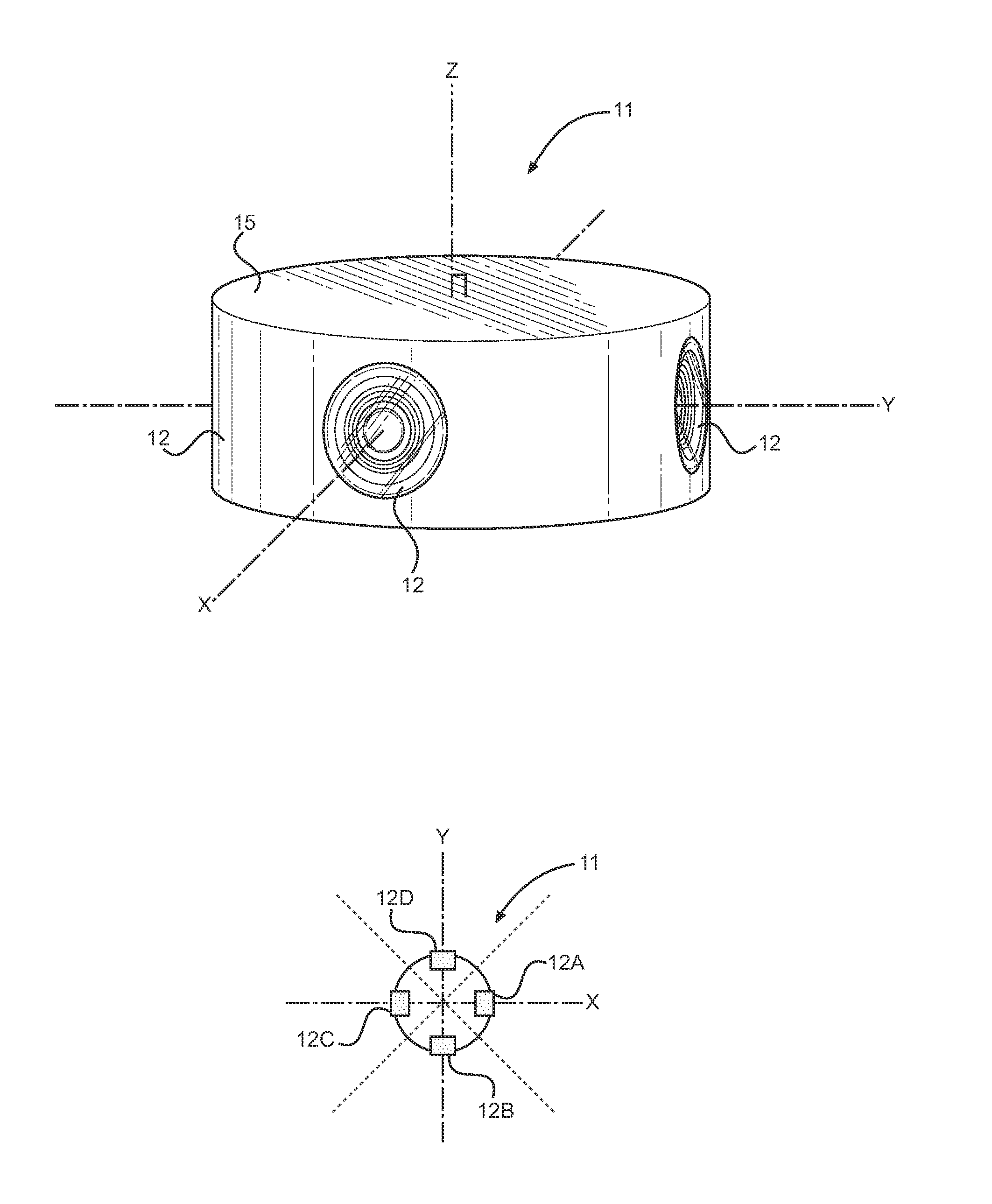
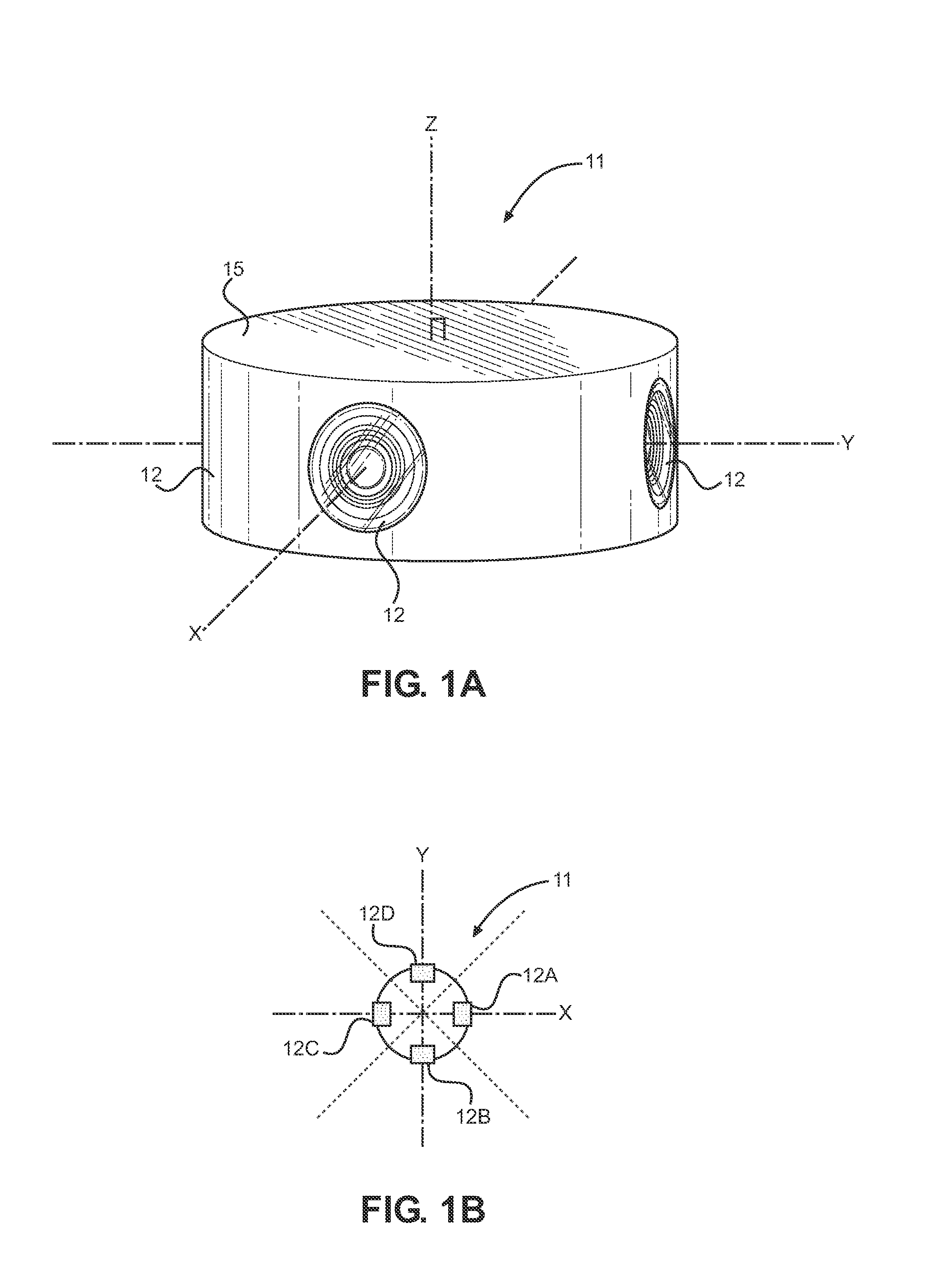
[0032]Referring now to FIGS. 1A and 2B, there are shown perspective and overhead views of the camera housing portion of the present invention. The present invention comprises a housing 11 with a plurality of non-rotational, aligned cameras 12 disposed around the perimeter of the housing 11 such that said cameras 12 are arranged to capture video in a 360 degree radius around the vertical axis of the housing 11. In the depicted embodiment of the present invention, the housing 11 is a cylindr...


PUM


Abstract

A video surveillance system adapted for use with vehicles is provided. The present invention comprises a housing having a plurality of cameras disposed around its periphery, a means for multiplexing the captured video footage into a single video feed, a removable storage medium that is preferably directly connected to the housing via a video cable or other such video transmitter. Furthermore, the present invention is either permanently or removably affixed to an individual's automobile. Each of the cameras is non-rotational, but they have a field of view such that the entire 360 degree area surrounding the present invention is simultaneously and continuously recorded. The present invention thereby provides an uninterrupted and complete video record of all of the events that occurred surrounding the user's vehicle.

Description

CROSS REFERENCE TO RELATED APPLICATION[0001]This application claims the benefit of U.S. Provisional Application No. 61 / 826,807 filed on May 23, 2013, entitled “Auto Cam.” The above identified patent application is herein incorporated by reference in its entirety to provide continuity of disclosure.BACKGROUND OF THE INVENTION[0002]1. Field of the Invention[0003]The present invention relates to video recording devices. More specifically, the present invention relates to video recording devices that are adapted to be attached to the top surface of a car and have a three hundred and sixty degree field of vision.[0004]It is often desirable to have a video record of events that occur to vehicle, such as a car accident or if an individual attempts to break into the vehicle. A video record of a car accident can quickly and easily resolve disputes between drivers and provide visual evidence for police officers or insurance companies. Furthermore, a video record of an attempted or successful ...

Claims


Application Information

Patent Timeline
Patent Type & Authority Applications(United States)
IPC IPC(8): B60R11/04H04N5/232
CPCH04N5/23238B60R11/04B60R2011/004H04N23/58H04N23/51
Inventor HATCHER, SYLVESTER
Owner HATCHER SYLVESTER
Learn More