Power conversion apparatus and power conversion method

a technology of power conversion apparatus and power conversion method, which is applied in the direction of power conversion system, dc-dc conversion, instruments, etc., can solve the problems of reducing the power conversion efficiency between the primary side circuit and the secondary side circuit, and achieve the effect of suppressing the reduction of power conversion efficiency

Active Publication Date: 2014-11-27
TOYOTA JIDOSHA KK
View PDF13 Cites 10 Cited by
  • Summary
  • Abstract
  • Description
  • Claims
  • Application Information

AI Technical Summary

Benefits of technology

[0010]According to each aspect of the invention, it is possible to suppress the reduction...

Problems solved by technology

However, when the phase difference between the switching of the primary side circuit and the switching of the secondary side circ...

Method used


Image

  • Power conversion apparatus and power conversion method
  • Power conversion apparatus and power conversion method
  • Power conversion apparatus and power conversion method

Examples


Embodiment Construction

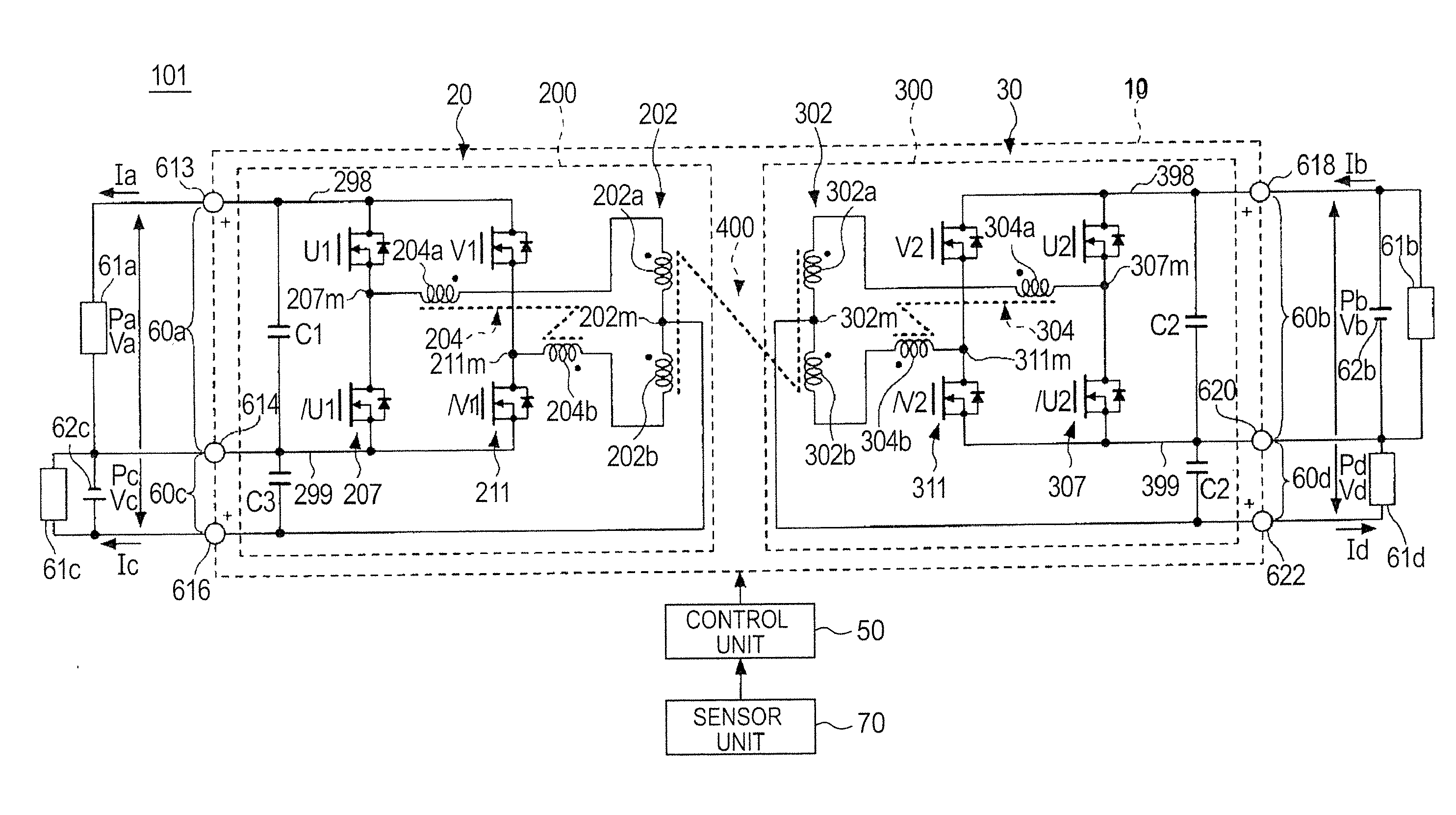
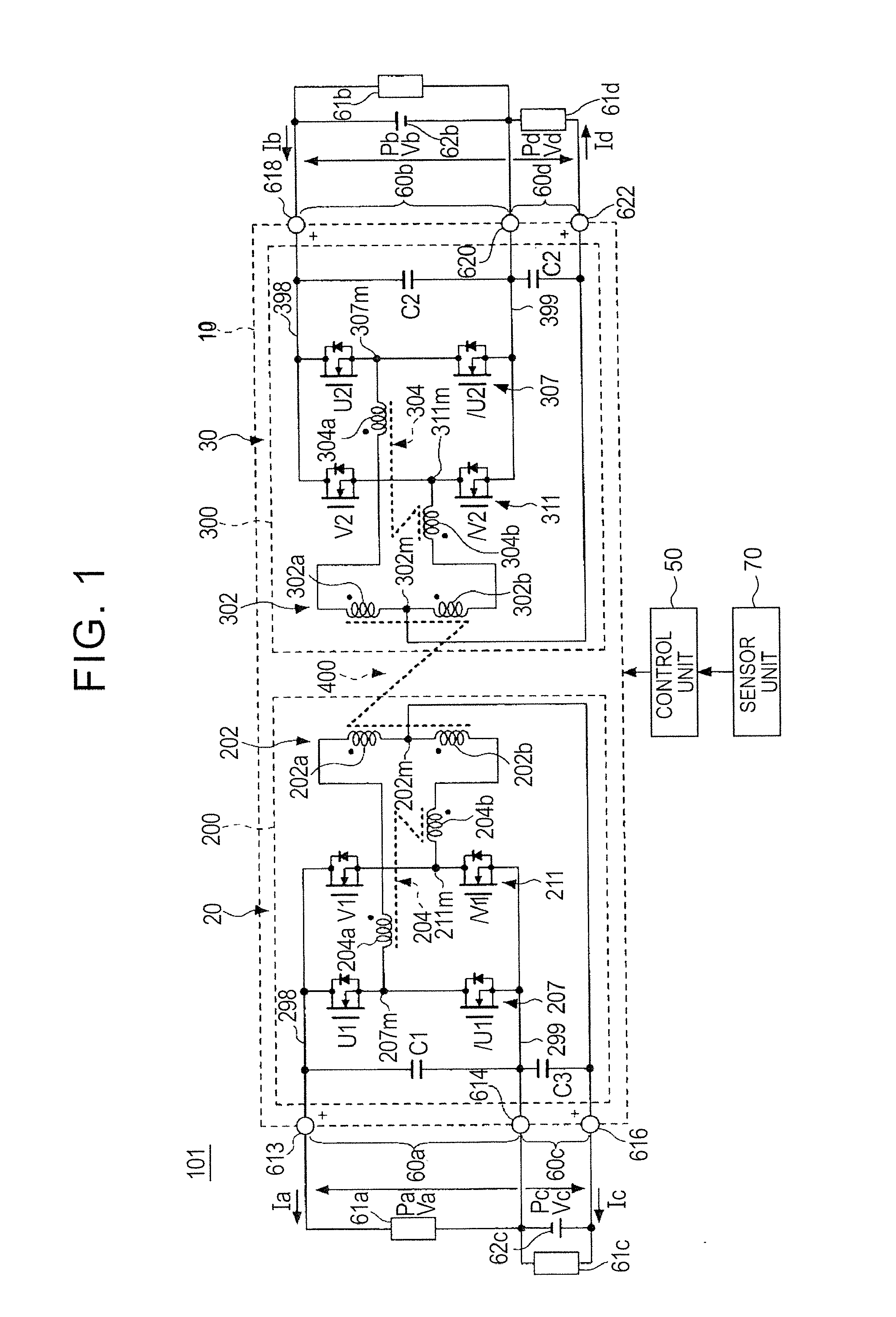
[0017]FIG. 1 is a block diagram showing an example of a configuration of a power supply apparatus 101 serving as an embodiment of a power conversion apparatus. For example, the power supply apparatus 101 is a power supply system that includes a power supply circuit 10, a control unit 50, and a sensor unit 70.

[0018]For example, the power supply apparatus 101 includes, as primary side ports, a first input / output port 60a to which a primary side high voltage system load 61a is connected and a second input / output port 60c to which a primary side low voltage system load 61c and a primary side low voltage system power supply 62c are connected. The primary side low voltage system power supply 62c supplies power to the primary side low voltage system load 61c, which is operated by an identical voltage system (a 12 V system, for example) to the primary side low voltage system power supply 62c. Further, the primary side low voltage system power supply 62c supplies power stepped up by a primar...


PUM


Abstract

A power conversion apparatus includes a primary side circuit and a secondary side circuit magnetically coupled to the primary side circuit via a transformer, and converts power between a primary side port of the primary side circuit and a secondary side port of the secondary side circuit, using switching of each of the primary side circuit and the secondary side circuit. The power conversion apparatus further includes a control unit that controls a frequency of the switching and a phase difference between the switching of the primary side circuit and the switching of the secondary side circuit such that power conversion efficiency between the primary side port and the secondary side port is increased.

Description

INCORPORATION BY REFERENCE[0001]The disclosure of Japanese Patent Application No. 2013-107415 filed on May 21, 2013 including the specification, drawings and abstract is incorporated herein by reference in its entirety.BACKGROUND OF THE INVENTION[0002]1. Field of the Invention[0003]The invention relates to a power conversion performed between a primary side circuit and a secondary side circuit that is magnetically coupled to the primary side circuit via a transformer.[0004]2. Description of Related Art[0005]A conventional power conversion apparatus can adjust an amount of power transmitted between a primary side circuit and a secondary side circuit by changing a phase difference between a switching operation of the primary side circuit and a switching operation of the secondary side circuit (see Japanese Patent Application Publication No. 2011-193713 (JP 2011-193713 A), for example).SUMMARY OF THE INVENTION[0006]However, when the phase difference between the switching of the primary...

Claims


Application Information

Patent Timeline
IPC IPC(8): H02M3/335
CPCH02M3/33546H02M3/33584H02M3/33561
Inventor MUTO, JUN
Owner TOYOTA JIDOSHA KK
Why Eureka
Try Eureka