High voltage direct current transmission and distribution system

a direct current transmission and distribution system technology, applied in the field of power distribution, can solve the problems of excessive losses, large voltage spikes along the cable length, and compromise the insulation of the cable itself as well as the insulation

Active Publication Date: 2014-11-27
EATON INTELLIGENT POWER LTD
View PDF0 Cites 41 Cited by
  • Summary
  • Abstract
  • Description
  • Claims
  • Application Information

AI Technical Summary

Benefits of technology

[0011]These needs and others are also met by embodiments of the disclosed concept in which a circuit interrupter for a power circuit of a high voltage direct current distribution system comprises a controller cooperating with the series combination of a solid-state switch and an electromechanical isolation switch to open, close and trip open the power circuit, the controller being structured to repetitively turn on and turn off the solid-state switch when the electromechanical isolation switch is closed, in order to control charging of the power circuit from zero volts to a high direct current voltage.
[0012]In accordance with one aspect of the disclosed concept, a high voltage direct current transmission and distribution system comprises: an alternating current to direct current converter including an alternating current input and a direct current output; a first high voltage direct current cable including a first end electrically connected to the direct current output of the alternating current to direct current converter and an opposite second end; and a distribution system comprising: a number of high voltage direct current circuit breakers, each of the number of high voltage direct current circuit breakers including a first portion electrically connected to the opposite second end of the first high voltage direct current cable and a second portion; a number of second high voltage direct current cables, each of the number of second high voltage direct current cables including a first end electrically connected to the second portion of a corresponding one of the number of high voltage direct current circuit breakers and an opposite second end; a number of galvanically isolated direct current to direct current converters, each of the number of galvanically isolated direct current to direct current converters including a direct current input electrically connected to the opposite second end of a corresponding one of the number of second high voltage direct current cables and a direct current output; a number of direct current to alternating current voltage source inverters, each of the number of direct current to alternating current voltage source inverters including a direct current input electrically connected to the direct current output of a corresponding one of the number of galvanically isolated direct current to direct current converters and an alternating current output; a number of alternating current transmission lines, each of the number of alternating current transmission lines including a first end electrically connected to the alternating current output of a corresponding one of the number of direct current to alternating current voltage source inverters and an opposite second end; and a number of alternating current loads, each of the number of alternating current loads electrically connected to the opposite second end of a corresponding one of the number of alternating current transmission lines, wherein each of the number of direct current to alternating current voltage source inverters is mounted in an enclosure with a corresponding one of the number of galvanically isolated direct current to direct current converters, in order that the direct current output of the last such corresponding one of the number of galvanically isolated direct current to direct current converters is directly electrically connected within the enclosure to the direct current input of a corresponding one of the number of direct current to alternating current voltage source inverters.
[0013]As another aspect of the disclosed concept, a direct current to alternating current inverter sub-system is for a high voltage direct current distribution system. The direct current to alternating current inverter sub-system comprises: an enclosure; a direct current to direct current galvanically isolated buck converter including a direct current input electrically connectable to a high voltage direct current cable and a direct current output; and a direct current to alternating current voltage source inverter including a direct current input electrically connected to the direct current output of the direct current to direct current galvanically isolated buck converter and an alternating current output electrically connectable to an alternating current transmission line, wherein the direct current to alternating current voltage source inverter is mounted in the enclosure with the direct current to direct current galvanically isolated buck converter, in order that the direct current output of the direct current to direct current galvanically isolated buck converter is directly electrically connected within the enclosure to the direct current input of the direct current to alternating current voltage source inverter.
[0014]As another aspect of the disclosed concept, a circuit interrupter for a power circuit of a high voltage direct current distribution system comprises: a first terminal; a second terminal; an electromechanical isolation switch; a solid-state switch electrically connected in series with the electromechanical isolation switch between the first and second terminals; and a controller cooperating with the solid-state switch and the electromechanical isolation switch to open, close and trip open the power circuit, the controller being structured to repetitively turn on and turn off the solid-state switch when the electromechanical isolation switch is closed, in order to control charging of the power circuit from zero volts to a high direct current voltage.

Problems solved by technology

In long transmission lines and, in particular, in ones that use cable, high voltage DC power transmission may be the only feasible method of power transmission because using AC will cause debilitating instability and excessive losses.
When connecting a DC voltage source to a relatively long cable transmission line when the cable capacitance is discharged, relatively large oscillatory currents occur which, in turn, generate relatively large voltage spikes along the cable length.
These voltage spikes can compromise the insulation of the cable itself as well as the insulation of any device electrically connected thereto.
Furthermore, the relatively large oscillatory currents can cause nuisance tripping of protection devices of the transmission line.

Method used


Image

  • High voltage direct current transmission and distribution system
  • High voltage direct current transmission and distribution system
  • High voltage direct current transmission and distribution system

Examples


example 1

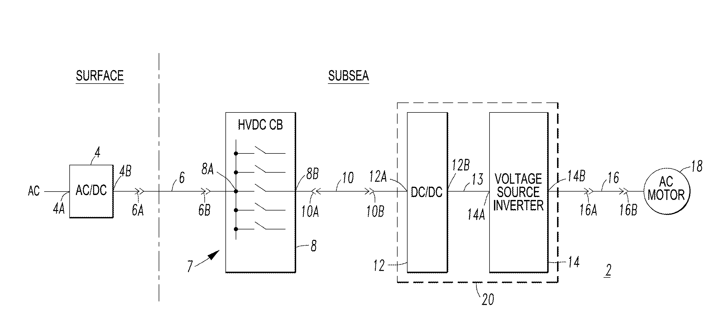
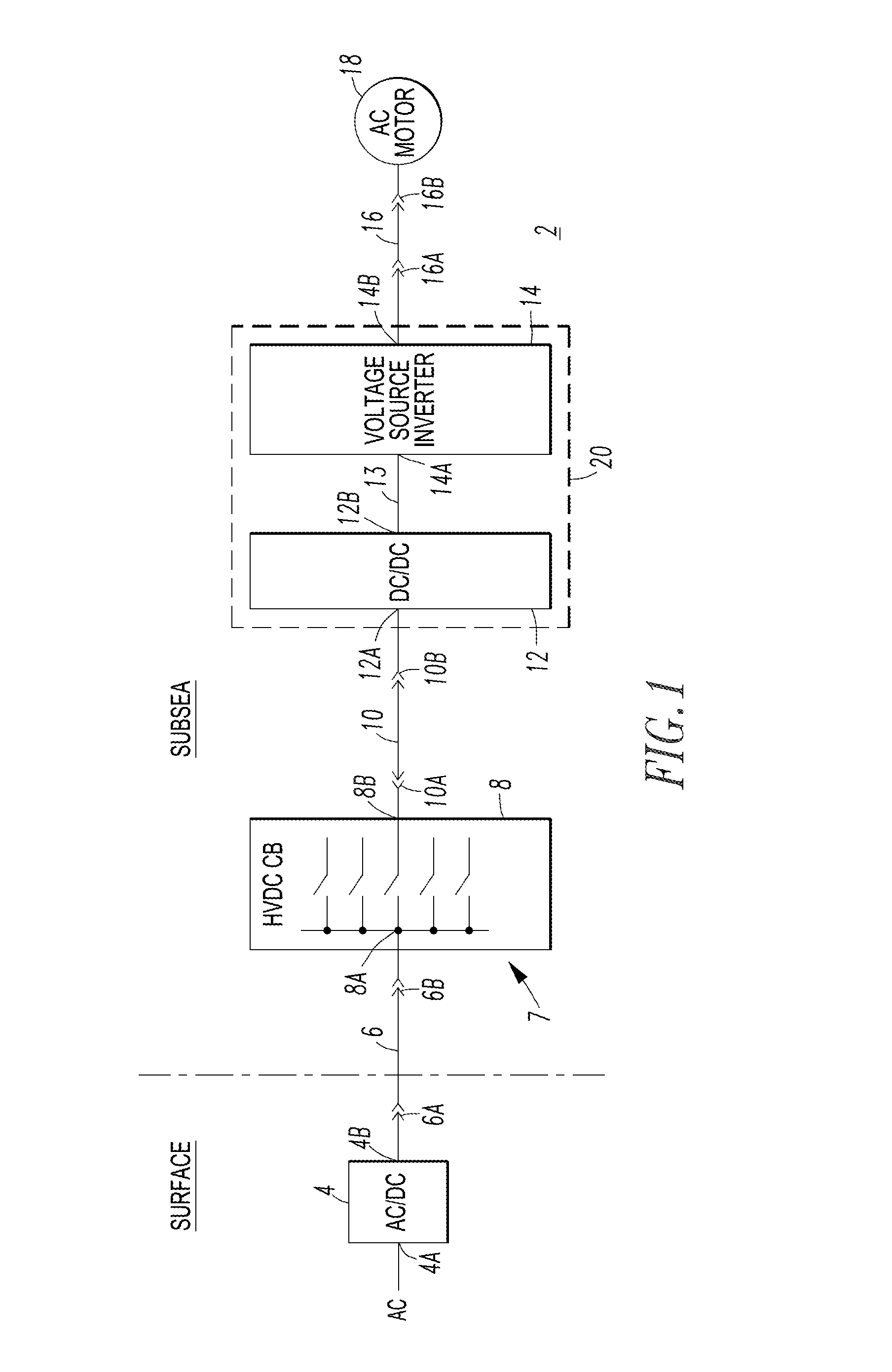
[0036]The AC / DC converter 4 can be installed on or above the surface of the sea or underwater (e.g., subsea) and is structured to ramp the DC voltage of the DC output 4B at a limited rate in order to avoid high voltage transients in the transmission line of the HVDC cable 6 during its energization. In the case of underwater installation, there is an isolation transformer (not shown) on a platform (not shown) and a multi-pulse transformer and converter (not shown) underwater. This configuration minimizes the ground current at the source.

[0037]The HVDC circuit breaker 8, the HVDC cable 10, the galvanically isolated DC / DC converter 12, the DC / AC voltage source inverter 14, the enclosure 20, the AC transmission line 16, and the AC load 18 are either subsea or below ground.

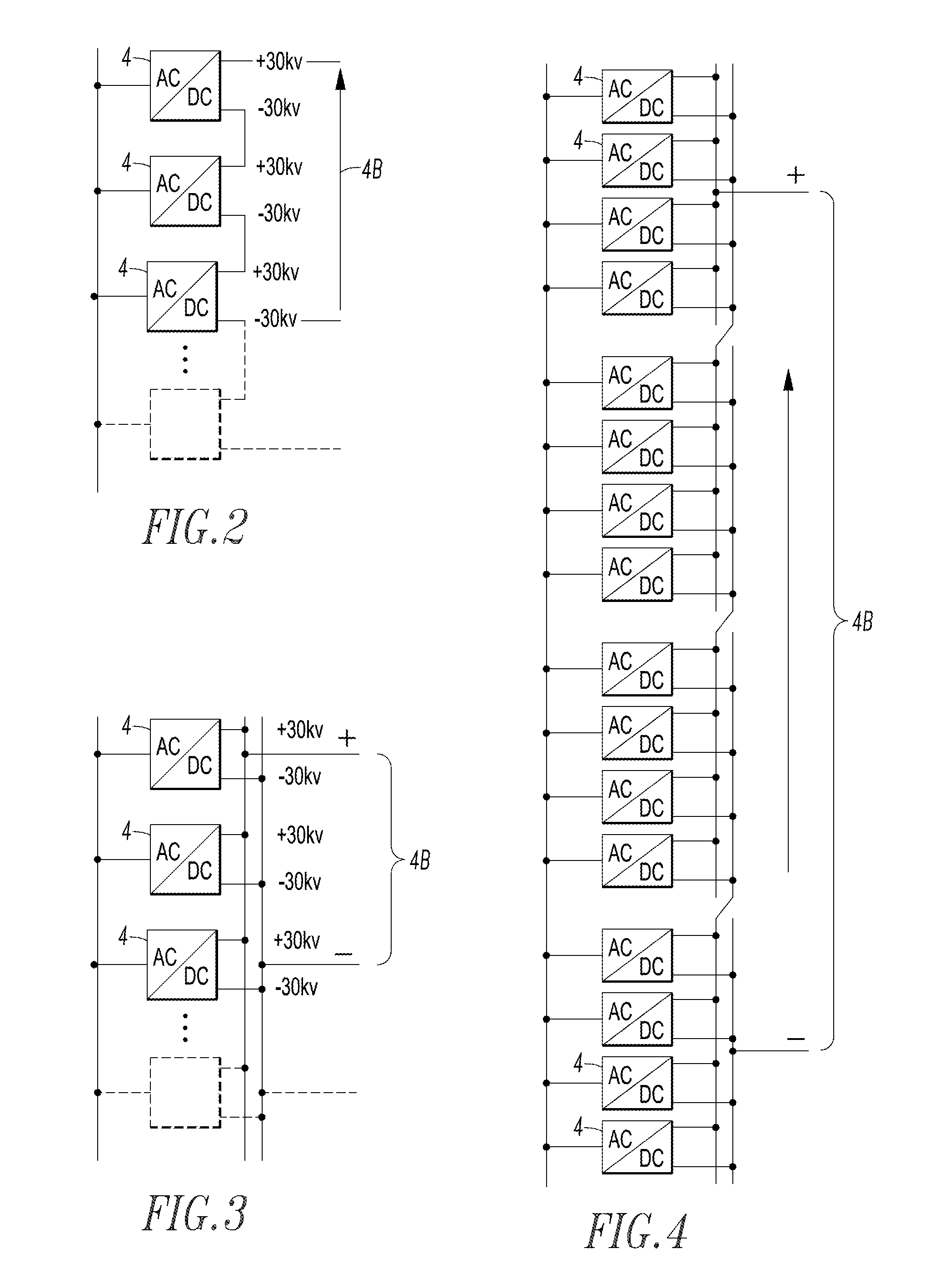
[0038]As a non-limiting example, the typical output voltage of the AC / DC converter 4 is + / −5 kV to + / −30 kV and the AC / DC converter 4 can be connected in series (FIG. 2), in parallel (FIG. 3) or in series and in parall...

example 2

[0041]The HVDC cable 6 employs bipolar transmission, and can be partially above ground and partially below ground, partially above sea and partially subsea, entirely subsea, or entirely below ground. For example, FIG. 5 shows another system 2′ in which the HVDC cable 6′ is partially above sea and partially subsea. No unipolar transmission is allowed in subsea or below ground applications due to galvanic corrosion of components of the enclosures involved.

example 3

[0042]The HVDC circuit breaker 8 includes a cable pre-charge function to prevent high voltage transients in the transmission line of the HVDC cable 10. The HVDC circuit breaker 8 protects a number of branch circuits (e.g., FIG. 5 shows a plurality of branch circuits of plural HVDC cables 10) derived off of the main HVDC transmission line of HVDC cable 6′, and pulse width modulates the output 8B to charge the downstream load side transmission line of the HVDC cable 10 to prevent high voltage transients due to cable length. A fault current generated due to a short circuit in the transmission line of the HVDC cable 10 or the input 12A of the galvanically isolated DC / DC buck converter 12 will be contained and isolated by the HVDC circuit breaker 8. As a result, the DC circuit breaker solid-state switches (e.g., 26 of FIG. 16) are turned off to protect the downstream power circuit from excessive energy.

[0043]The transmission line of the HVDC cable 10 contains resistive 10R, inductive 10L...


PUM


Abstract

A direct current to alternating current inverter sub-system is for a HVDC distribution system. The DC to AC inverter sub-system includes an enclosure and a DC to DC galvanically isolated buck converter having a DC input electrically connectable to a HVDC cable and a DC output. A DC to AC inverter includes a DC input electrically connected to the DC output of the DC to DC galvanically isolated buck converter and an AC output electrically connectable to an AC transmission line. The DC to AC inverter is mounted in an enclosure with the DC to DC galvanically isolated buck converter, in order that the DC output of the DC to DC galvanically isolated buck converter is directly electrically connected within the enclosure to the DC input of the DC to AC inverter.

Description

BACKGROUND[0001]1. Field[0002]The disclosed concept pertains generally to power distribution and, more particularly, to high voltage direct current transmission and distribution systems, such as, for example, such systems for above ground, below ground or subsea applications. The disclosed concept further pertains to circuit interrupters for high voltage direct current distribution systems.[0003]2. Background Information[0004]Alternating current (AC) power distribution systems are well known.[0005]High voltage, direct current (DC) power distribution systems have less energy losses and require less costly transmission cables than corresponding AC distribution systems. In long transmission lines and, in particular, in ones that use cable, high voltage DC power transmission may be the only feasible method of power transmission because using AC will cause debilitating instability and excessive losses.[0006]When connecting a DC voltage source to a relatively long cable transmission line ...

Claims


Application Information

Patent Timeline
Patent Type & Authority Applications(United States)
IPC IPC(8): H02J3/36
CPCH02J3/36H01H9/548H01H33/596H02H11/005H02J2003/365Y02E60/60
Inventor BROUSSARD, HARRYNOJIMA, GERALDO
Owner EATON INTELLIGENT POWER LTD
Why Eureka
Try Eureka