Plasma spray apparatus integrating water cleaning

a technology of spray apparatus and spraying water, which is applied in the direction of plasma technique, cleaning using liquids, coatings, etc., can solve the problems of dust particles on the substrate surface, poor adhesion of the applied coating, and additional maintenance, and equipment capital expenditur

Inactive Publication Date: 2014-11-27
PROGRESSIVE SURFACE
View PDF4 Cites 2 Cited by
  • Summary
  • Abstract
  • Description
  • Claims
  • Application Information

AI Technical Summary

Problems solved by technology

Otherwise, the applied coating has poor adhesion and will spall or flake off.
Additionally, the grit-blasting process leaves dust particulates on the substrate surface that needs to be removed prior to applying a coating.
Instead, separate equipment is typically used, resulting in additional capital expenditure for equipment, additional maintenance, and a less efficient process flow since the plasma torch / treating process must be shut off (or redirected) while separate equipment is used to clean loosely adhered particulates.
In some existing processes, a person or robot may enter into a work area to clean loosely adhered particulates, which can result in possible introduction of contaminants and process inconsistencies.
A reason the plasma jet alone is not used to blow loosely adhered particulates off a substrate is because the heat from the plasma can partially melt these particulates, causing an increase in adhesion of the undesirable material to the substrate, making it more difficult to remove the undesirable material.
Also, even though the adhesion of the undesirable material is increased, the adhering strength may still be much lower strength than is necessary for good coating adhesion.
Also, the undesirable material is unlikely to be in the proper form (e.g. phase or morphology) for a good coating.
Similarly, a plasma torch is not used to propel blasting media at a substrate because the media would melt and form a coating on the substrate rather than clean it.

Method used


Image

  • Plasma spray apparatus integrating water cleaning
  • Plasma spray apparatus integrating water cleaning

Examples


Embodiment Construction

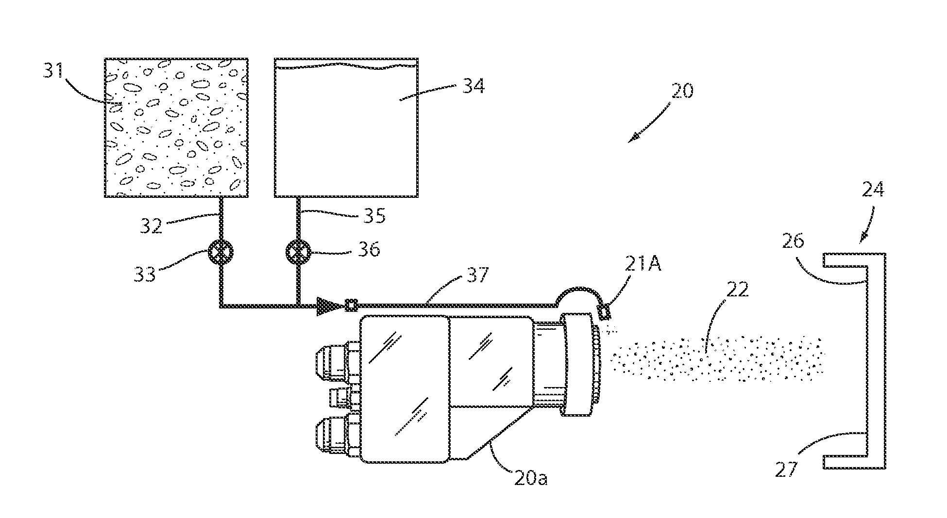
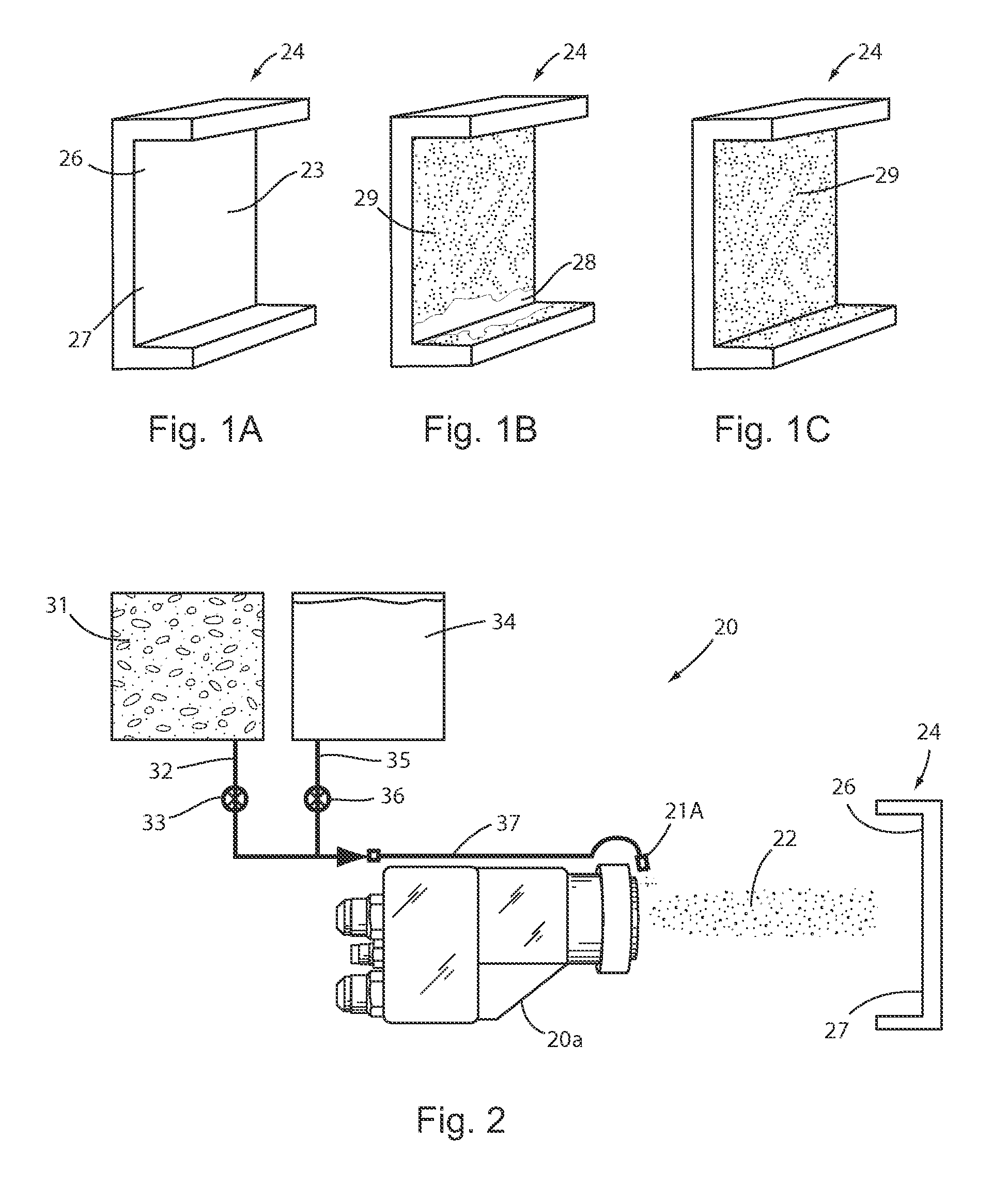
[0016]The present apparatus 20 and method incorporating the present innovative technology of a liquid (e.g. water) injected into the plume 22 of a thermal treatment process have been tested to effectively and efficiently clean debris 28 and loose undesired material from a surface 23 of a part 24, thus improving treatment of the surface 23 on a part 24. The cleaning is particularly useful in a suspension plasma spray (SPS) process for treating non-planar surfaces, such as where a plasma torch 20a applies surface treating plasma to a part 24 having a part geometry similar to that in FIG. 1A and FIG. 2. However, it is believed that a scope of the present innovation is broader than just suspension plasma spray processes. Specifically, while treating a surface 23 on the upper portion 26 of the illustrated part 24, such as when applying a coating 29, a dust-like overspray material 28 can be produced that lands on the adjacent lower portion 27 (and / or the upper portion 26) of part surfaces...


PUM

PropertyMeasurementUnit
temperaturesaaaaaaaaaa
temperatureaaaaaaaaaa
adhesionaaaaaaaaaa

Abstract

An integrated apparatus and method comprises a plasma gun with a water supply, treatment fluid supply, and controls, the combination of which is adapted for directing a plume onto a surface of a three-dimensional part to treat the surface; and for controlling injection of water into the plume with the plume directed onto an adjacent surface to clean debris and undesired material from the adjacent surface; and for subsequently directing the plume (without water) onto the adjacent surface to treat the adjacent surface. The apparatus and method are particularly useful in suspension plasma spray systems, but are not believed to be limited to that.

Description

CROSS REFERENCE TO RELATED APPLICATIONS[0001]This application is a continuing application of U.S. patent application Ser. No. 13 / 826,252, filed Mar. 14, 2013, entitled “PLASMA SPRAY APPARATUS INTEGRATING WATER CLEANING,” which claims benefit and priority to U.S. Provisional Patent Application No. 61 / 639,471 filed Apr. 27, 2012, entitled PLASMA SPRAY APPARATUS INTEGRATING WATER CLEANING, the entire contents of which are incorporated herein.BACKGROUND[0002]The present invention relates to plasma spray apparatus, and more particularly relates to a plasma spray apparatus integrating water cleaning of contaminants and overspray.[0003]Plasma spray coatings adhere to a substrate primarily by mechanical forces. Thus, for optimal coating performance, loose debris such as grit blasting residue remaining from surface preparation or overspray generated during a coating process should be removed from the substrate prior to applying a coating. Otherwise, the applied coating has poor adhesion and ...

Claims


Application Information

Patent Timeline
Patent Type & Authority Applications(United States)
IPC IPC(8): C23C4/12
CPCC23C4/12C23C4/127C23C4/134B08B3/026
Inventor VANEVERY, KENT
Owner PROGRESSIVE SURFACE
Why Eureka
Try Eureka