

Prosthesis Seals and Methods for Sealing an Expandable Prosthesis
a prosthesis and expansion valve technology, applied in the field of prosthesis, can solve the problems of difficult to provide a perfectly sealing fit between the stent-valve and the surrounding anatomy, and the native anatomy is even more irregular, so as to achieve good strength and resistance to bursting, the effect of reducing the risk of bursting
- Summary
- Abstract
- Description
- Claims
- Application Information
AI Technical Summary
Benefits of technology
Problems solved by technology
Method used
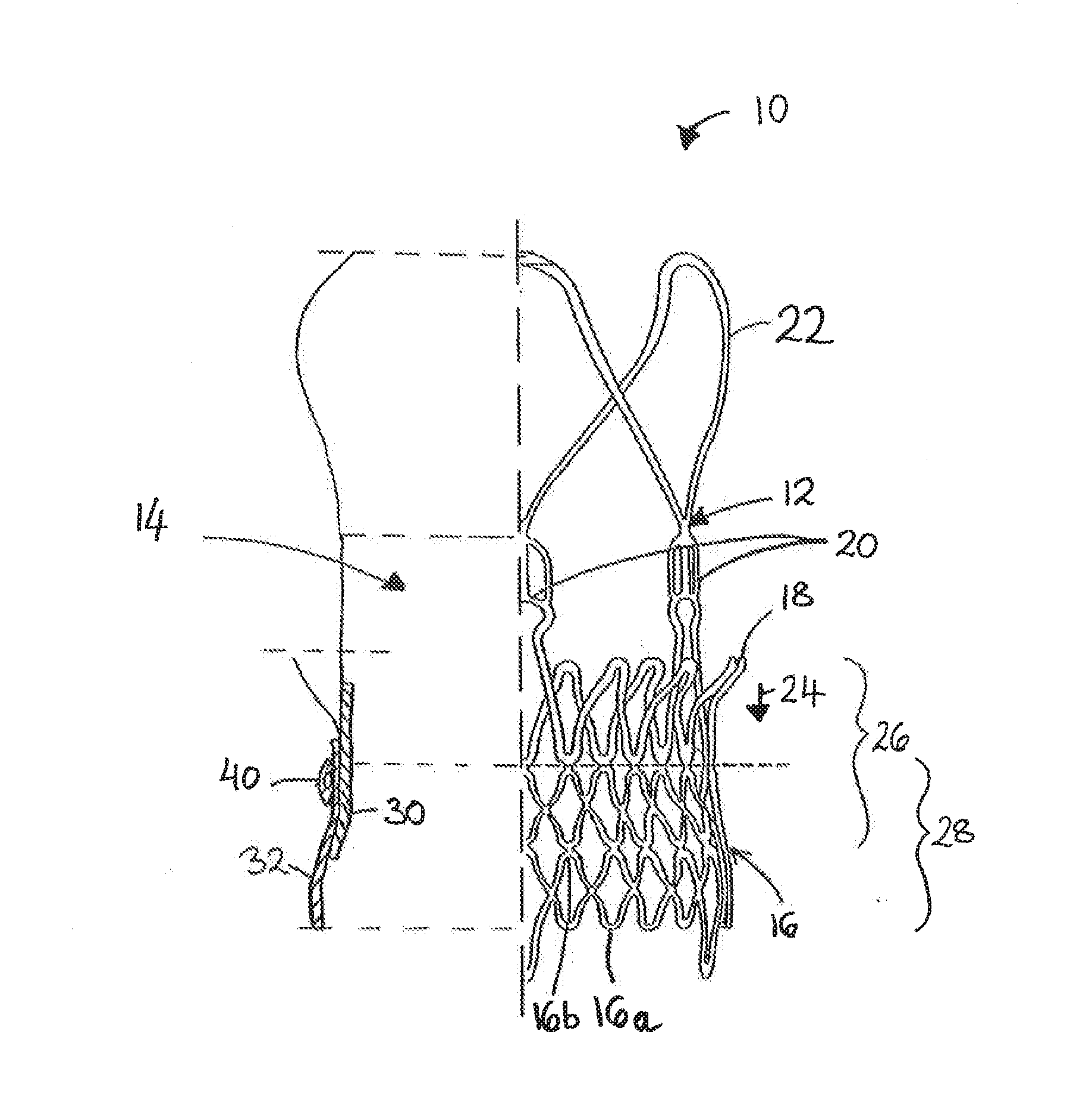
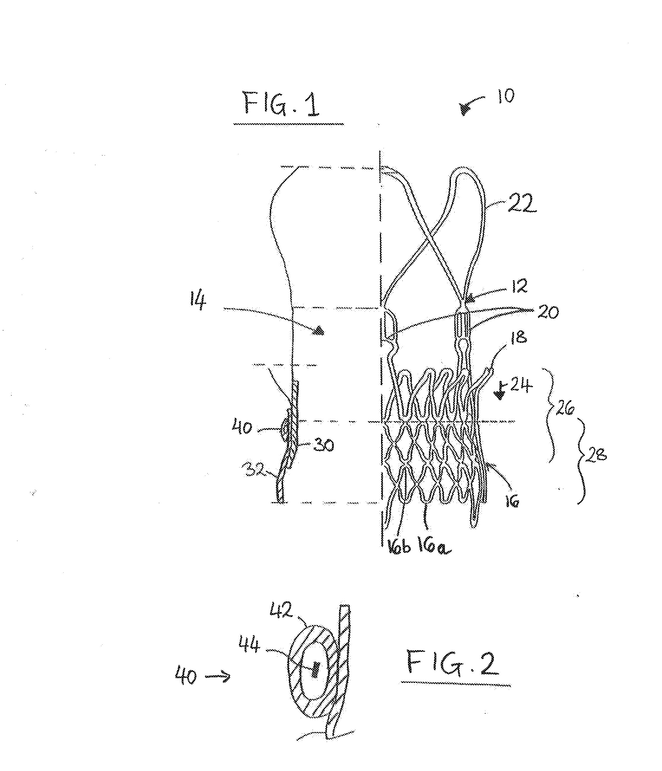
Image

Examples
Embodiment Construction
[0012]The following disclosure presents a summary of the invention in order to provide a basic, non-limiting, understanding of some embodiments of the invention.
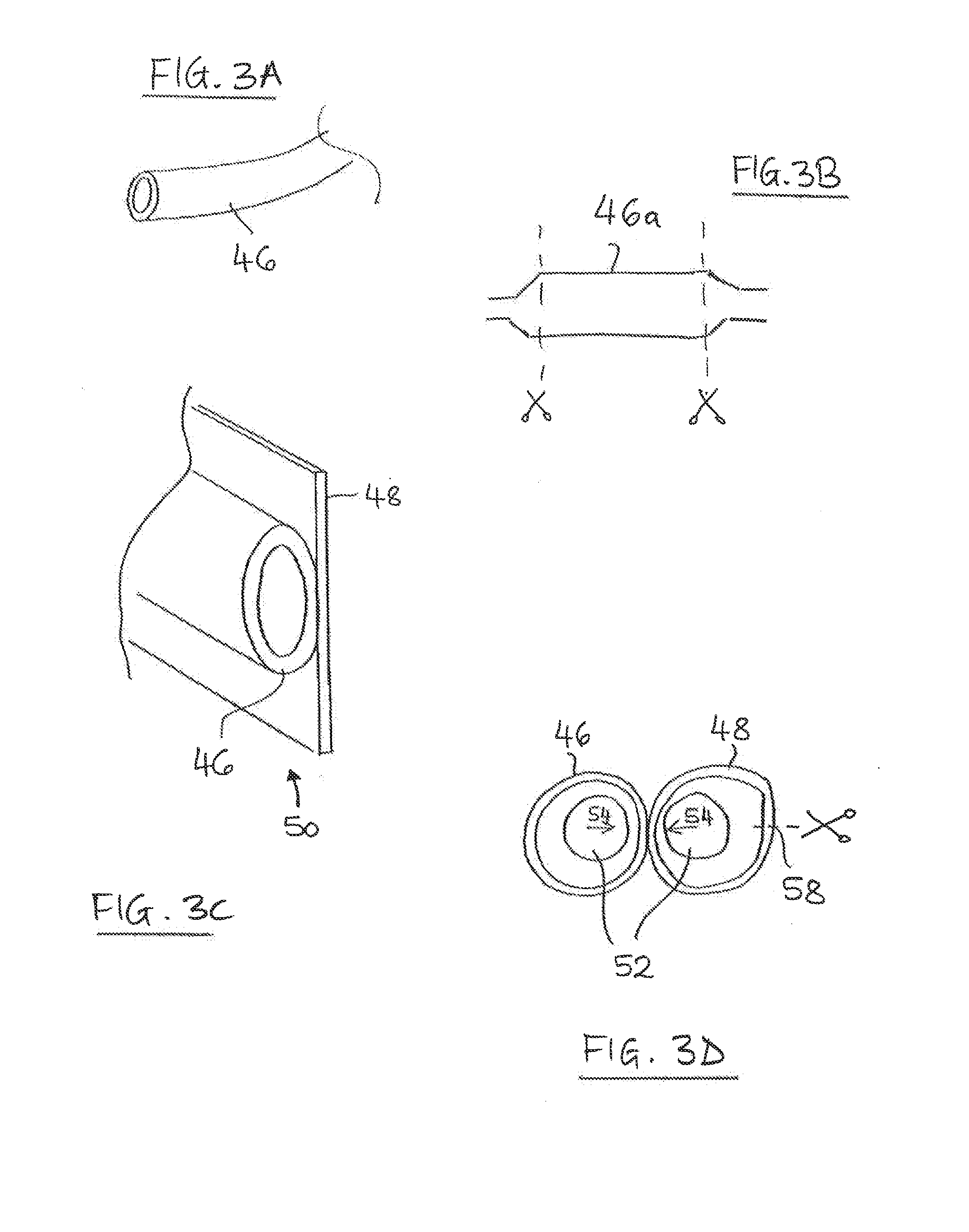
[0013]For example, in some embodiments of the present disclosure, a seal is provided for a prosthesis. The seal may be configured for obstructing para-prosthesis leakage. The prosthesis may, for example be a stent-valve (for example a cardiac stent-valve, such as an aortic stent-valve). The seal may comprise one or any combination of two or more of the following features, which are all optional. The list of optional features is bulleted by dashes (“-”).[0014]In some embodiments, the seal is provided as a separate item from the prosthesis. The separate seal may be mountable on the prosthesis prior to implantation of the prosthesis. For example, the seal may be mountable on the prosthesis as part of a pre-implantation preparation process.[0015]Alternatively, the seal may be provided as an integral part of the prosthesis.[0016]...
PUM
 Abstract
Description
Claims
Application Information