Angle measuring device and methods for calibration

Active Publication Date: 2014-11-27
DIGIPAS TECH INC
View PDF22 Cites 16 Cited by
  • Summary
  • Abstract
  • Description
  • Claims
  • Application Information

AI Technical Summary

Benefits of technology

[0020]A further object of the present invention is to provide a system and method for changing a measurement state of a digital level having an orientation sensor. The system and method includes detecting an orientation of the digital level through the orientation sensor and automatically activating a measurement mode of the digital level based on the orientation detected

Problems solved by technology

Driven by automobile, semiconductor and clean energy of precision engineering industries, the demand for tighter tolerance machining part—higher precision), High speed machining—vibration becomes important issue affecting machine's accuracy, High volume machining and complex machined part—production yield significantly affecting cost and delivery lead time, Larger size of machined part and harder materials, have emerged as critical variables influencing these advanced CNC machines accuracy performance and machine—part production yield requirements.
Machinists are still using the traditional single-axis ‘bubble’ spirit level or conventional single-axis digital leveling instrument to perform machine leveling tasks which are unarguably ineffective—time consuming, skilled-operator dependent, and difficult to verify machine leveling status when machine setup activity completed.
First, the task confronted by the machine operator for leveling a machine is a two-dimensional planar surface alignment issue. In contrast, traditional leveling and angle measuring instruments are single axis or one directional. Machine leveling operator is required to adjust a machine-frame footings one axis at a time. Since aligning a machine structure involves planar surface, adjusting one axis of the machine affect the other axis of existing plane. Thus, the operator has to do trial-and-error by going back-and-forth in adjusting each footing until the machine surface plane (i.e. where the leveling instrument is placed) is completely leveled. This is a tedious, time consuming and nonproductive task, yet critical affecting machine accuracy and yield performance. The operator could potentially resort to compromise in facing such lengthy repetitive task of iteration.
Second, leveling a machine using traditional spirit level or digital level typically requires two operators. One operator looks

Method used


Image

  • Angle measuring device and methods for calibration
  • Angle measuring device and methods for calibration
  • Angle measuring device and methods for calibration

Examples


Embodiment Construction

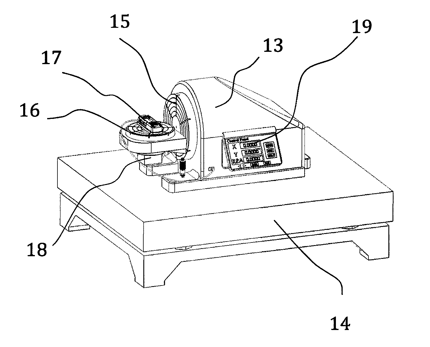
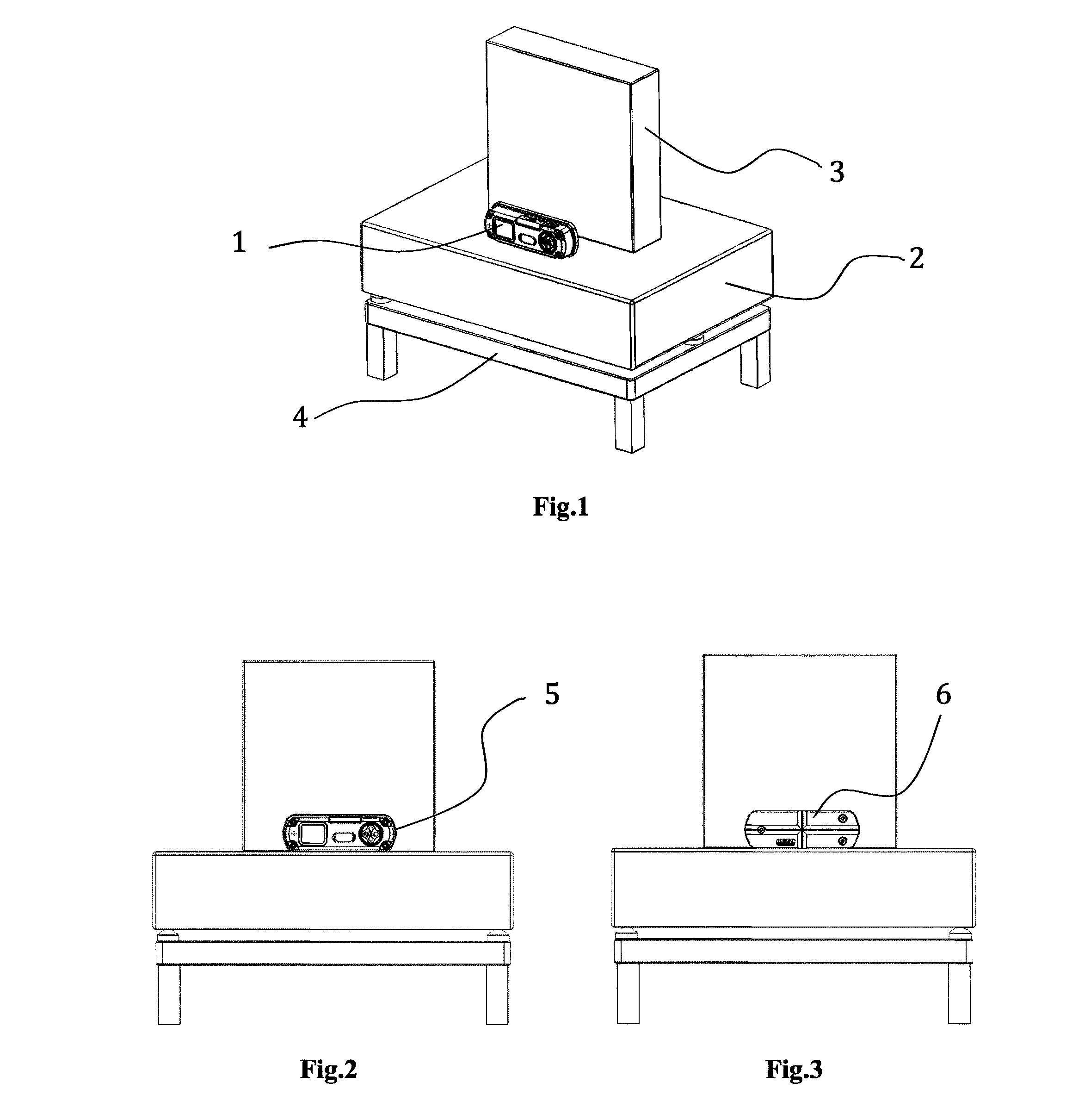
[0034]The calibration method used for setting the 2-axis digital angle measuring instrument is to configure both X and Y sensors reference angular plane positions as shown in FIG. 1 to FIG. 9. The digital angle measuring instrument or device may include any of a variety of orientation sensors that may be disposed in the device, for example in one or more microelectromechanical systems (MEMS) chips or the like. For example, the orientation sensors may include vibration sensors for detecting vibration magnitude in X, Y and Z directions of the cartesian coordinate system, azimuth sensors for detecting angular position change in one or more directions or in parallelism measurements, weight or pressure sensors, or any other desired orientation sensors such as accelerometers or gyroscopes. According to FIG. 1, the 2-axis digital level 1 is preferably placed on a levelled granite table 2 and a granite master square 3 supported by a metal frame 4.

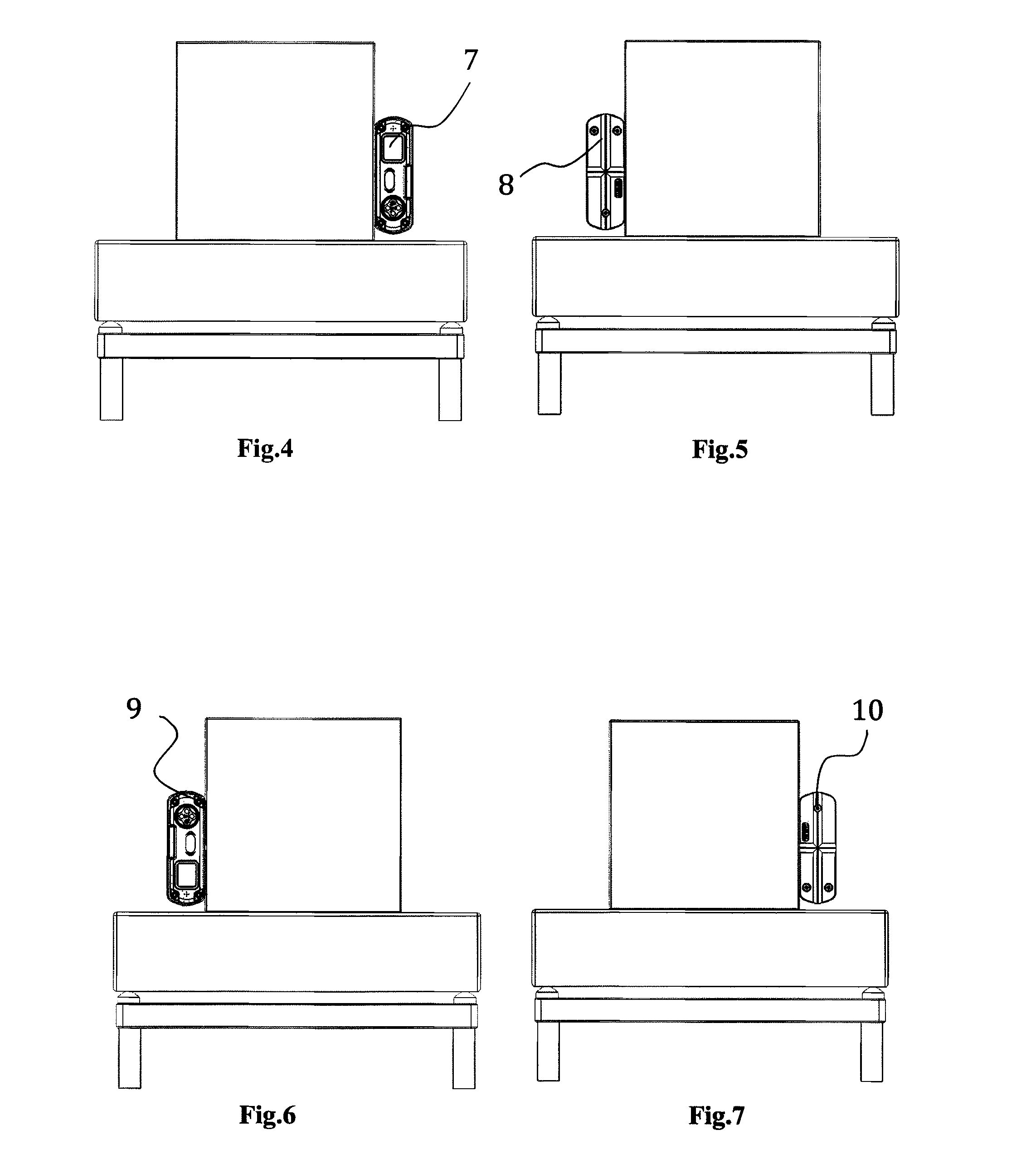
[0035]According to FIG. 2 to FIG. 9 illustra...


PUM


Abstract

The invention relates to a method for calibration of 2-axis high precision digital angle measurement device, particularly for initializing a planar angle measuring device and an apparatus to generate simultaneous two-dimensional resultant planar angles of full 360° rotation. The planar angle measurement device is, typically but not exclusively, used in concurrent two-dimensional angles leveling, setting and alignment tasks for precision machine setup in the fields of precision engineering and metrology applications.

Description

BACKGROUND OF INVENTION[0001]1. Field of Invention[0002]This invention concerns leveling and angle measuring devices, apparatus and methods for calibration.[0003]2. Description of Prior Art[0004]Traditional precision machining utilizing turning lathe, drilling and milling machines were typically operated by skilled machinist through precise adjusting each X, Y and Z axis to complete a machining component or part. These skilled-labor dependent machines has been radically replaced by very high precision, augmented machining speed, multiple axis, fully automatic computer numerical control (CNC) machines. These programmable CNC machines are capable of non-stop running in production lines integrated with automatic robotic manipulators for material input and removing the machined part.[0005]Driven by automobile, semiconductor and clean energy of precision engineering industries, the demand for tighter tolerance machining part—higher precision), High speed machining—vibration becomes impor...

Claims


Application Information

Patent Timeline
IPC IPC(8): G01C25/00
CPCG01C25/00G01C25/005
Inventor HONG, JIM LI HUIYONG, KUU BI
Owner DIGIPAS TECH INC
Why Eureka
Try Eureka