De-humidifying system

a technology of dehumidification system and wind turbine, which is applied in the direction of mechanical equipment, machines/engines, electric generator control, etc., can solve the problems of hindering water and moisture from entering the tower, affecting the heating and ventilation of the interior of the wind turbine, and affecting the efficiency of the wind turbine. , to achieve the effect of reducing the relative humidity inside the tower, avoiding the entry of moisture or rain into the tower, and optimizing the heating and ventilation of the interior of the tower

Inactive Publication Date: 2014-12-04
MELALEUCA INC
View PDF0 Cites 11 Cited by
  • Summary
  • Abstract
  • Description
  • Claims
  • Application Information

AI Technical Summary

Benefits of technology

[0013]From the chamber, the air can flow through the second tube through the through-hole in the tower wall to the exterior of the tower. A through-hole in the tower wall can easily be planned and arranged by cutting a hole in the tower wall or by preparing the part of the tower wall during fabrication. Thus, the through-hole provides an easier access for the air into the tubes and the chamber. The tower comprises a door, and a first tube and/or the second tube are connected to a through-hole in a door. Thus, the through-holes are arranged in the door and no additional through-holes through the tower wall are needed. Thus, the tower wall is not weakened by the through-holes.
[0014]A first pressure sensor is arranged outside the tower and the second pressure sensor is arranged inside the tower. The entry of moisture or rain into the tower can be avoided by keeping the tower interior at a higher pressure than the air pressure on the outside of the tower. A ventilator is arranged in the first tube or in the second tube and can press air into the interior of the tower through the valve. The pressure level inside of the tower can be controlled by the second pressure sensor and be compared to the pressure outside of the tower, measured by the first pressure sensor. The valve is controlled in a way that the interior of the tower is kept at a higher pressure than the air pressure around the tower. The first pressure sensor and the second pressure sensor are connected to a pressure control unit, and the pressure control unit comprises a connection to the valve. The pressure control unit controls the valve in dependency on the pressure measured by the sensors. The first pressure sensor, measuring the air pressure at the outside of the tower, is connected to the control unit. The second pressure sensor, measuring the air pressure within the tower, is also connected to the control unit. The control unit is connected to the valve to control the valve. Thus, the air pressures outside of the tower and inside the tower are measured and a pressure difference can be calculated. The valve is controlled according to the pressure difference to keep the interior of the tower at a higher pressure than the air outside of the tower.
[0015]A normal wind turbine tower is not air-tight. Air can move into the tower and out of the tower through minor gaps. Gaps are present for example between the tower and the nacelle of the wind turbine, from the tower into the nacelle of the wind turbine, or at the door of the tower. Air is moving from the interior of the tower though the gaps to the outside of the tower when the interior of the tower is kept at a higher air pressure then the air surrounding the tower. Thus air is moving from the inside of the tower to the outside of the tower, and the air outside of the tower is kept from moving into the tower interior. Thus, air with a high

Problems solved by technology

Due to humidity in the ambient air and changing temperatures, humidity tends to condensate on cold surfaces in the wind turbine.
Such high humidity levels are unwanted, as the humidity is a problem for the electrical systems in the tower and for the tower itself.
It is therefore known to hinder water and moisture to get into the tower.
This shows the disadvantage that air from o

Method used


Image

  • De-humidifying system
  • De-humidifying system
  • De-humidifying system

Examples


Embodiment Construction

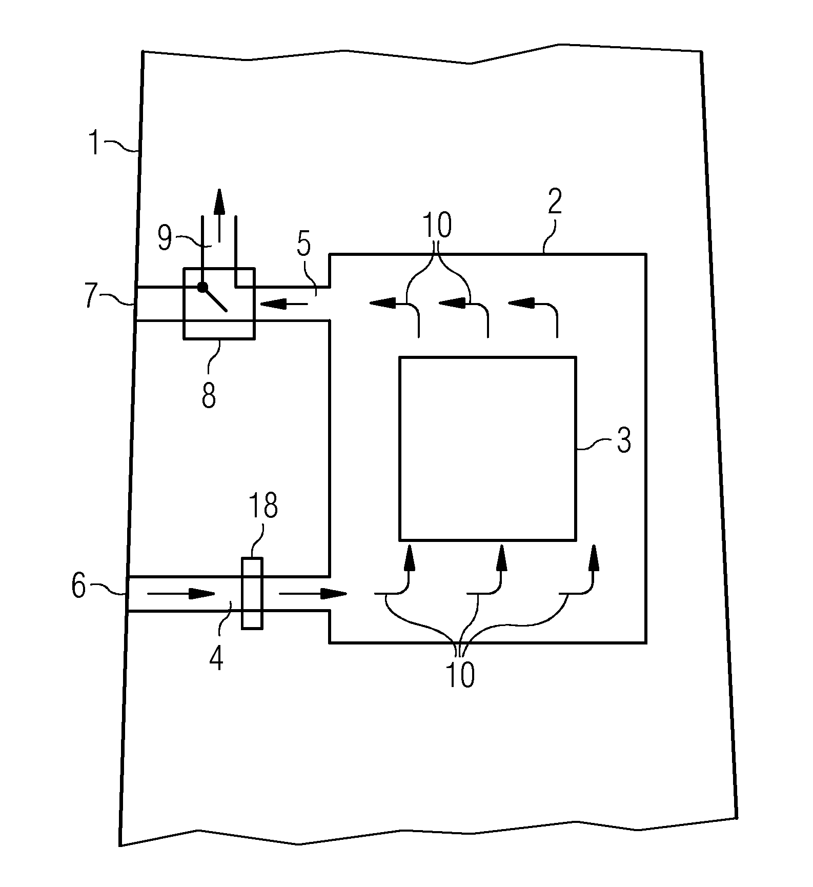
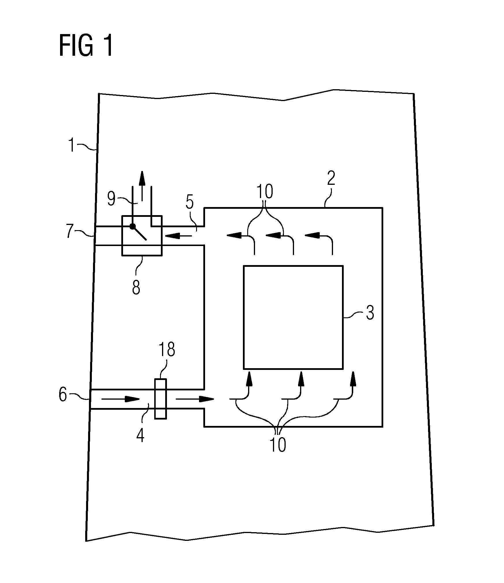
[0026]FIG. 1 shows a dehumidifying system of a wind turbine tower. The tower 1 comprises a chamber 2 with an electrical arrangement 3 that emits waste heat. The electrical arrangement 3 is cooled by an air flow 10.

[0027]A first tube 4 connects the interior of the chamber 2 to the exterior of the tower 1. The first tube 4 is connected to a through-hole 6 in the wall of the tower 1. The first tube 4 allows air to flow from the outside of the tower 1 into the chamber 2.

[0028]A second tube 5 connects the interior of the chamber 2 to the exterior of the tower 1. The second tube 5 is connected to a through-hole 7 in the tower wall. The second tube 5 allows air to flow from the chamber 2 to the exterior of the tower 1.

[0029]The air 10 flows through the through-hole 6 and the first tube 4 into the chamber 2. In the chamber 2 the air gets warmed by the electrical arrangement 3. The warm air flows along the second tube 5 and through the through-hole 7 to the exterior of the tower 1. A fan 18 ...


PUM


Abstract

The invention relates to a de-humidifying system of a wind turbine. In a wind turbine tower de-humidifying system the tower comprises a chamber in its interior. The chamber comprises an electrical arrangement that admits waste heat. A first tube connects the interior of the chamber to the exterior of the tower, to allow air from the exterior of the tower to flow into the chamber. A second tube connects the interior of the chamber to the exterior of the tower, to allow air from inside the chamber to flow to the exterior of the tower. A valve is arranged in the second tube to open a passage between the second tube and the interior of the tower, to allow air from the chamber to flow into the tower.

Description

CROSS-REFERENCE TO RELATED APPLICATIONS[0001]This application claims priority to EP Application No. 13169451.5, having a filing date of May 28, 2013, the entire contents of which are hereby incorporated by reference.FIELD OF TECHNOLOGY[0002]The invention relates to a de-humidifying system of a wind turbine.BACKGROUND[0003]A wind turbine comprises a wind turbine rotor with rotor blades. The rotor is attached to the nacelle of the wind turbine. The nacelle is arranged on top of a tower. Wind turbines are used on-shore or off-shore. On-shore wind turbines are often located close to a coast. In the off-shore area and close to a cost the humidity in the ambient air can be quite high. Due to humidity in the ambient air and changing temperatures, humidity tends to condensate on cold surfaces in the wind turbine. Especially in the tower of the wind turbine the humility level can reach a level, where corrosion or mould can build inside the tower. Such high humidity levels are unwanted, as th...

Claims


Application Information

Patent Timeline
IPC IPC(8): F03D9/00F03D11/00
CPCF03D9/002F03D11/0091F03D11/005F05B2260/64F05B2270/323F05B2270/324F05B2270/325F03D80/00F03D17/00F03D80/80F03D9/25Y02E10/72F03D80/60
Inventor SOERENSEN, CARSTEN MOELLER
Owner MELALEUCA INC
Why Eureka
Try Eureka