Method and apparatus for deriving current for control in a resonant power converter

a technology of resonant power converter and current control, applied in the direction of resistance/reactance/impedence, photovoltaic monitoring, instruments, etc., can solve the problems of unfavorable ct and increase parts and space requirements, and the difficulty of using a resistive shunt to monitor the current of the resonant tank

Active Publication Date: 2014-12-04
ENPHASE ENERGY
View PDF12 Cites 27 Cited by
  • Summary
  • Abstract
  • Description
  • Claims
  • Application Information

AI Technical Summary

Benefits of technology

[0009]Method and apparatus for measuring current in a resonant converter substantially as shown and / or described in connection with at least one of the figures as set forth more completely in the claims.

Problems solved by technology

While the CT provides galvanic isolation and reduces noise in the measured signal, the CT undesirably raises the cost of parts and space requirements.
Hence, any current shunt signal is likely to be in the millivolt range which is troublesome as the resistive shunt will be subjected to common mode noise and high input voltage being fed into the converter.
Using a resistive shunt to monitor the resonant tank current is challenging as any monitoring circuit must measure the voltage using a low signal to noise ratio (SNR).

Method used


Image

  • Method and apparatus for deriving current for control in a resonant power converter
  • Method and apparatus for deriving current for control in a resonant power converter
  • Method and apparatus for deriving current for control in a resonant power converter

Examples


Embodiment Construction

[0017]Embodiments of the present invention comprise a balanced current monitoring circuit coupled across a capacitor within a resonant circuit of a resonant power converter. Embodiments may be comprised of full or half-bridge power converters.

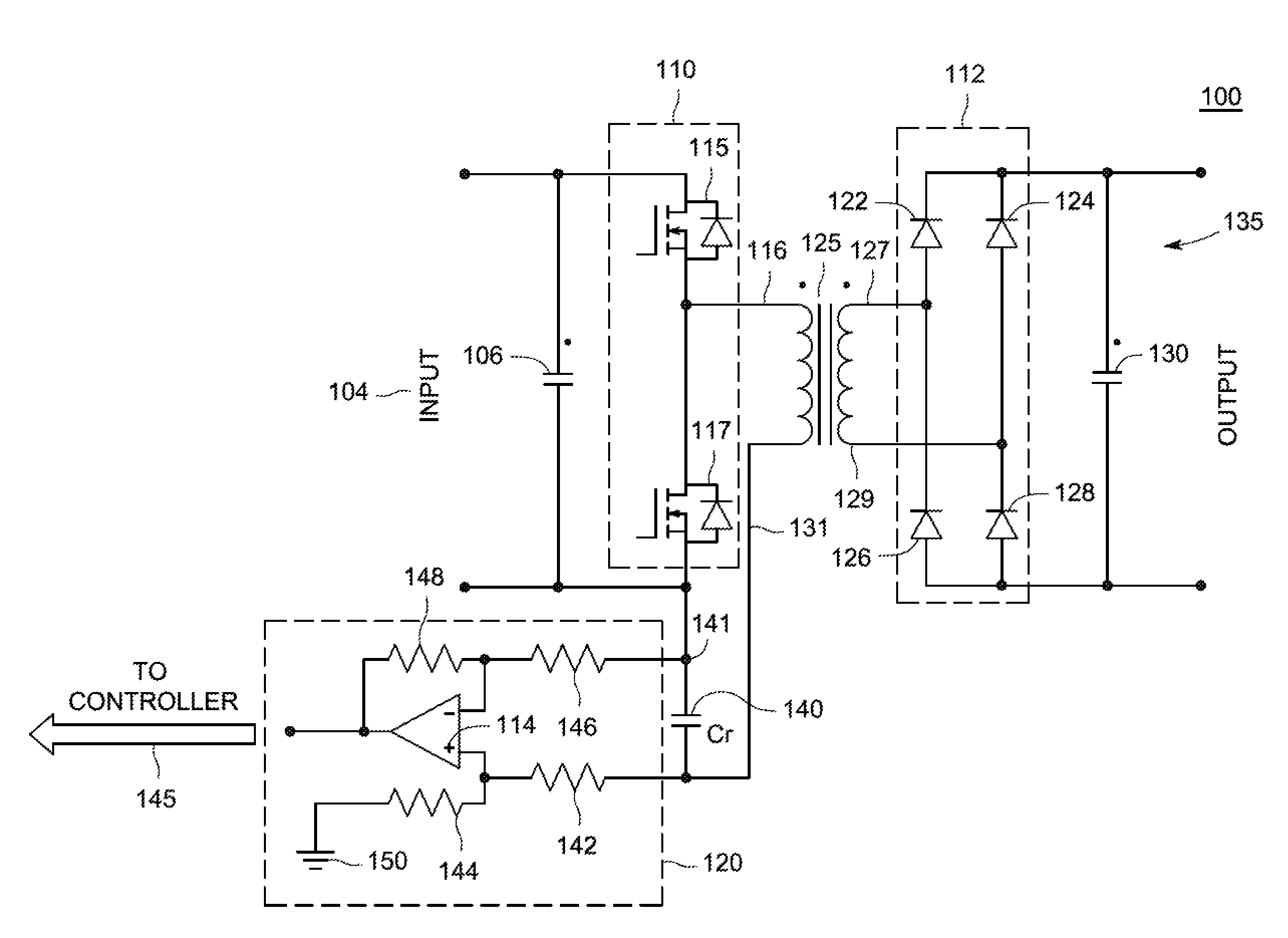
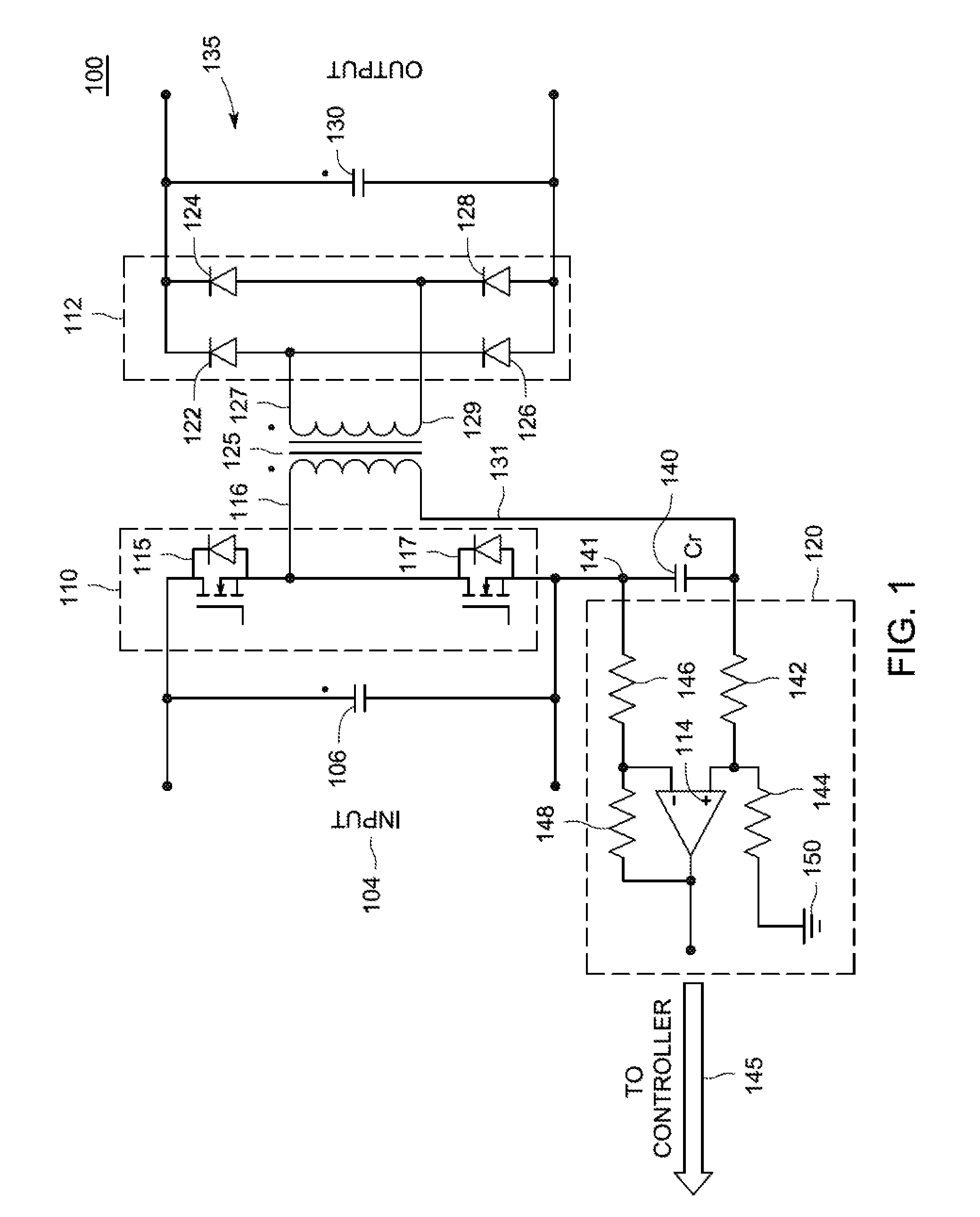
[0018]FIG. 1 is a schematic of a resonant converter 100 in accordance with one or more embodiments of the present invention. The converter 100 is described as outputting a DC output, however other embodiments include AC output, single phase or multi-phase outputs (e.g., split-phase or three-phase). The converter 100 comprises an input port 104, an input capacitor 106, a half-bridge circuit 110, a tank capacitor 140, transformer 125, diode bridge circuit 112, output capacitor 130, output port 135, controller 145, and a voltage measuring circuit 120.

[0019]The half-bridge circuit 110 comprises switch 115 and switch 117 in series coupled across the input port 104 and input capacitor 106. A first leg 116 of a primary winding of the transformer 125 i...


PUM


Abstract

An apparatus, method, and system for measuring current within a converter. The converter including a resonant tank circuit with a capacitor, the resonant tank circuit is coupled to a DC input bridge and a first terminal of the capacitor is coupled to a ground of the DC input bridge. In addition, a voltage monitor coupled across the capacitor for measuring a voltage across the capacitor. The converter also includes a resonant current calculation module for computing a tank current value based on the voltage.

Description

CROSS-REFERENCE TO RELATED APPLICATION[0001]This application claims priority to U.S. Provisional Patent Application No. 61 / 828,761 filed on May 30, 2013, which is incorporated by reference herein in its entirety.BACKGROUND OF THE INVENTION[0002]1. Field of the Invention[0003]Embodiments of the present disclosure relate generally to power conversion and, in particular, to deriving a resonant current signal for controlling controlling a resonant tank current in a resonant converter.[0004]2. Description of the Related Art[0005]Resonant converters provide many advantages over other types of power converters. Such advantages may include low noise, low component stress, low component count, and predictable conduction-dominated losses. Resonant converters may therefore be smaller, less costly, and more efficient devices that other types of converters.[0006]The resonant converters typically comprise a bridge circuit, a resonant tank circuit, a transformer, and a current transformer (CT). Th...

Claims


Application Information

Patent Timeline
Patent Type & Authority Applications(United States)
IPC IPC(8): G01R19/00
CPCG01R19/00H02M3/3376H02S50/00H02M1/0009H02M1/0058Y02B70/10Y02E10/50
Inventor HARRISON, MICHAEL
Owner ENPHASE ENERGY
Why Eureka
Try Eureka