
Gaze tracking with projector

a projector and projector technology, applied in the field of projector-based projector-based projector-based projector-based projector-based projector-based projector-based projector-based projector-based projector-based projector-based projector-based projector-based projector-based projector-based projector-based projector-based projector-based projector-based projector-based projector-based projector-based projector-based projector-based projector-

Active Publication Date: 2014-12-04
SONY CORP
View PDF27 Cites 108 Cited by
  • Summary
  • Abstract
  • Description
  • Claims
  • Application Information

AI Technical Summary

Benefits of technology

The invention is about a system and method for gaze tracking using a head-mounted device with a projector and image-capturing module. The system can detect the reflection of light from the eye and determine the line of sight associated with it. The projector can also adjust the image based on the distance between the eye and the display. The technical effect of the invention is to provide a more precise and accurate means of gaze tracking for applications such as augmented reality and virtual reality.

Problems solved by technology

However, there are several disadvantages associated with using discrete IR LEDs to direct light into an eye.
In systems where the distance from the image-capturing module to the eye is very small, reflections (e.g., the glint) may be difficult to detect and / or track with high precision as the reflections become larger.
Additionally, an IR LED can occupy a substantial amount of space, and since space on a gaze tracking system may be limited, the system cannot accommodate several IR LEDs when several IR LEDs are required.
When the space on a system is limited, the system cannot accommodate several LEDs because the limited space prevents each LED from being separated from another LED by the predetermined distance.
Additionally, the angular range over which the direction of a gaze can be tracked is small because eye movement causes the reflection (e.g., the glint) to fall outside the spherical part of the cornea, which makes the detection of the reflection less reliable.

Method used


Image

  • Gaze tracking with projector
  • Gaze tracking with projector
  • Gaze tracking with projector

Examples


Embodiment Construction

[0023]Embodiments of the present invention now may be described more fully hereinafter with reference to the accompanying drawings, in which some, but not all, embodiments of the invention are shown. Indeed, the invention may be embodied in many different forms and should not be construed as limited to the embodiments set forth herein; rather, these embodiments are provided so that this disclosure may satisfy applicable legal requirements. Like numbers refer to like elements throughout.

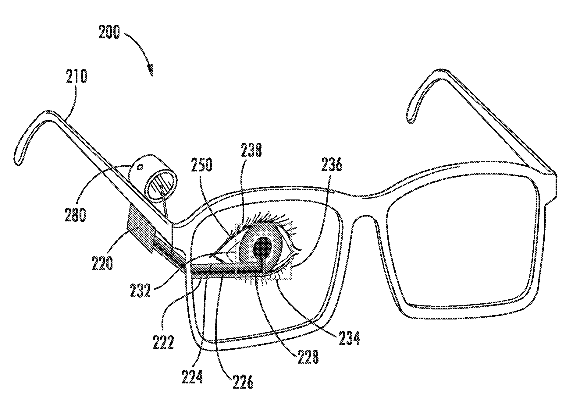
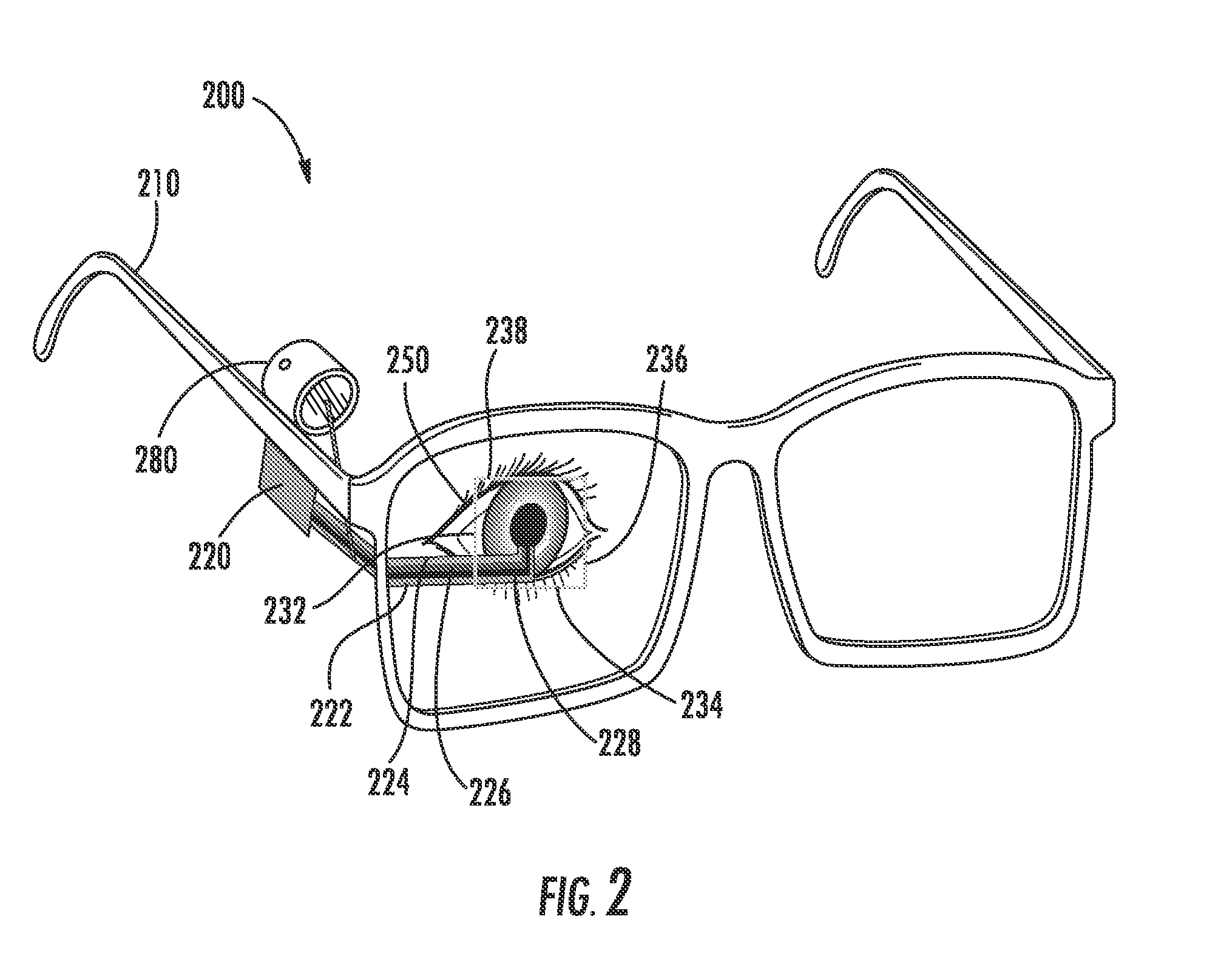
[0024]The invention is directed to systems, methods and computer program products for gaze tracking using non-contact optical techniques. As used herein, a non-contact technique is a technique where the gaze tracking system is not in physical contact with the eye. An exemplary method includes directing light into an eye using a projector; detecting, using an image-capturing module, a reflection from a surface associated with the eye (e.g., the glint); and determining a line of sight associated with th...


PUM


Abstract

The invention is directed to systems, methods and computer program products for gaze tracking. An exemplary method includes directing light into an eye using a projector; detecting, using an image-capturing module, a reflection from a surface associated with the eye; and determining a line of sight associated with the eye based on the detected reflection. In some embodiments, the light comprises infra-red light. In some embodiments, the projector comprises a laser. In some embodiments, the projector comprises a liquid crystal on silicon (LCoS) chip. In some embodiments, the surface associated with the reflection is at least one of the cornea, the iris, or the retina.

Description

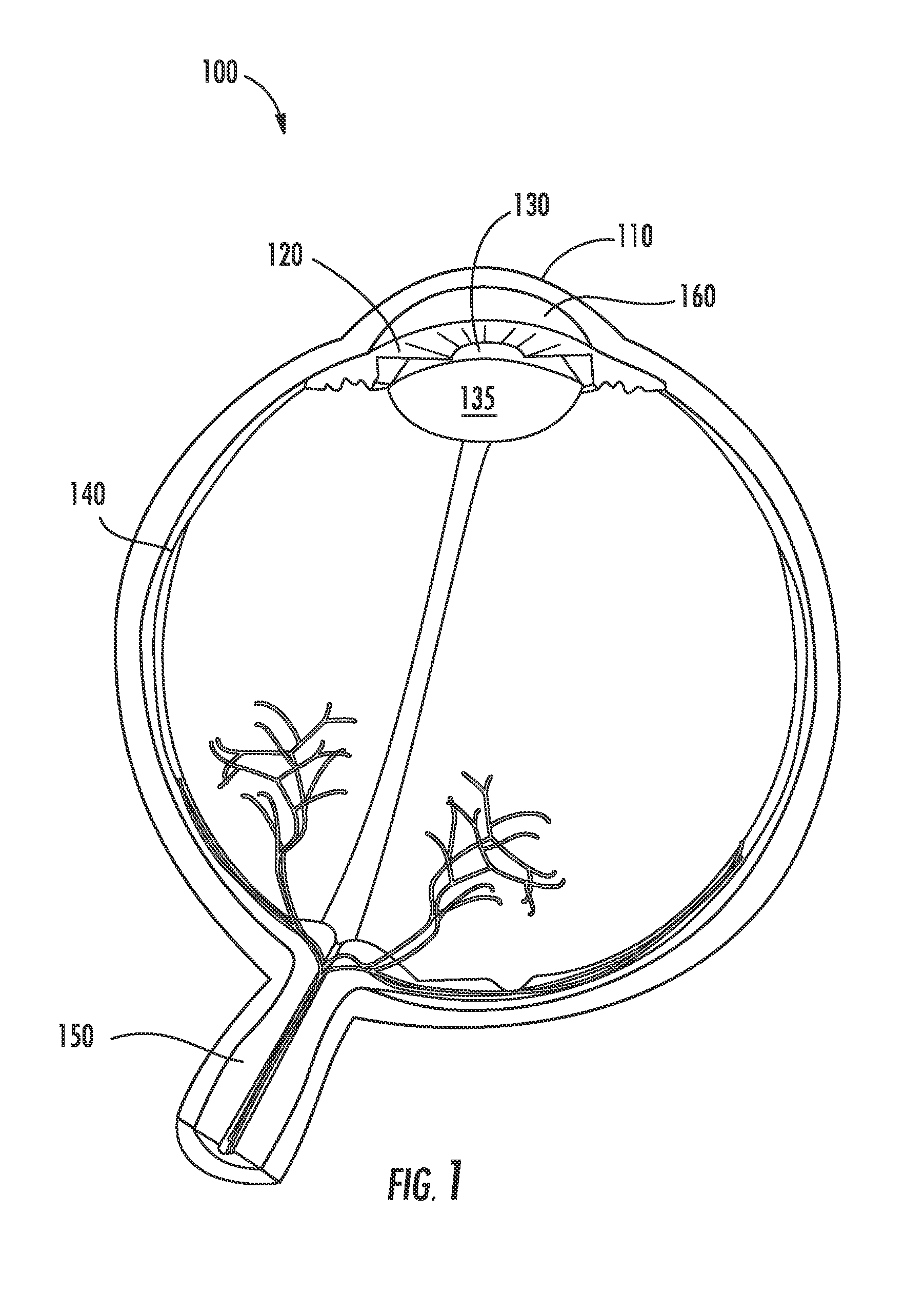
BACKGROUND[0001]As presented in FIG. 1, the important parts of a human eye 100 include the cornea 110, the iris 120, the pupil 130, the lens 135, the retina 140, and the optic nerve 150. The cornea 110 is the clear outer bulging surface at the front of the eye. The cornea 110 is the major refractive surface of the eye. The iris 120 is the colored part of the eye that regulates an amount of light entering the eye. The pupil 130 is the opening at the center of the iris 120. The iris 120 modifies or adjusts the size of the pupil 130 and thereby controls the amount of light that enters the eye. The lens 135 is the clear part of the eye behind the iris 120 that focuses light on the retina 140. The retina 140 is a light-sensitive tissue lining at the back of the eye. The retina 140 transforms light into electrical signals that are transmitted to the brain via the optic nerve. The aqueous humor 160 is a gelatinous fluid that is located in the space between the lens 135 and the cornea 110. ...

Claims


Application Information

Patent Timeline
Patent Type & Authority Applications(United States)
IPC IPC(8): G06F3/01G06T19/00H04N13/04G02B27/01H04N13/00
CPCG06F3/013G02B27/017H04N13/0022H04N13/044G02B2027/0187G06T19/006G02B2027/0138G02B2027/0178H04N13/0484G02B27/0172G02B2027/0185G06T2207/30041H04N13/128H04N13/344H04N13/383
Inventor ARONSSON, PAR-ANDERS
Owner SONY CORP
Learn More