Video endoscopic device

a technology of endoscope and video, which is applied in the field of video endoscope device, can solve the problems of inability to use instruments, and achieve the effects of improving image quality, reducing the number of instruments, and simplifying the assembly of the endoscope sha

Active Publication Date: 2014-12-04
XION
View PDF9 Cites 26 Cited by
  • Summary
  • Abstract
  • Description
  • Claims
  • Application Information

AI Technical Summary

Benefits of technology

[0023]An advantage of the invention is that the usual adaptation at size and location of the outlet pupil to the human eye with respect to the eyepieces used in the prior art is dispensed with. By way of example, the collimation can be achieved by rod lenses or rod lens systems at the light outlet of the elongate shaft of the stereo endoscope. Furthermore, compared to other lens systems, an advantage offered by rod lenses or rod lens system is that the transmission of a substantially brighter image with higher image quality is made possible. The assembly in the endoscope shaft is also simplified due to the elongate geometry of the rod lenses. The arrangement of two parallel beam paths extending closely next to one another is also possible for small shaft diameters. A deterioration in the image quality at the edge can also be avoided well. It is possible to correct the off-axis image aberrations such as coma and astigmatism by means of the video endoscopic device according to the invention. A further advantage of the invention consists of the fact that a lateral distance between the stereoscopic partial images in the recording plane can be set virtually arbitrarily, even if the distance between the stereoscopic partial images is very small in the objectives at the distal end. As a result, it is possible to construct a versatile stereo endoscopic system. In accordance with a respective medical application, a respective camera head can be connected to different interchangeable endoscopes, each with a different stereoscopic base length. Moreover, the optical system according to the invention has a lower sensitivity towards tolerances. As a result of this, the demands on the mechanical accuracy of a connection of the camera head are reduced compared to stereo endoscopes from the prior art.
[0024]In a preferred configuration, the optical arrangements are arranged in a rigid endoscope shaft; in this case, the optical components arranged coaxially with one another are arranged along a longitudinal axis of the endoscope shaft. Alternatively, the endoscope shaft can also have a flexible configuration, for example as a tube, as a collar-surrounded tube or the like. For a flexible endoscope shaft, the optical components arranged coaxially with one another are arranged along the rigid straight longitudinal axis of the endoscope shaft in a rigid straight state of the endoscope shaft. By generating curvature along the endoscope shaft, for example by insertion into a lumen and bending of the endoscope shaft, the optical components are displaced in accordance with the curvature of the endoscope shaft.
[0025]The at least approximately parallel beam path at the outlet of the respective optical arrangement can have a deviation from the ideal collimation of up to + / −10 dioptre without this impairing the stereoscopic display. Both the beam path from each one of the collimating optical units and the beam paths of the collimating optical units may be only approximately and not completely parallel to one another, i.e. have a deviation, for example due to manufacturing tolerances. By way of example, the resulting tolerance in the collimation between the left-hand and right-hand beam path can be compensated for when focusing the camera head. Alternatively or additionally, there can also be tuning of the collimation of both approximately parallel beam paths by adjusting the axial distances between two or more optical components, e.g. rod lens systems.
[0026]The optical components arranged coaxially with one another are preferably rod lens systems. The rod lens systems may be rod lenses cemented to one another. It is also feasible to cement rod lenses with other lenses for producing a rod lens system. The optical components arranged coaxially with one another can also be rod lenses. Alternatively or additionally, the optical components may have other lenses or optical elements.
[0027]In a preferred configuration, all optical components of the optical arrangement, the collimating optical unit, the objectives and the projection objectives or a projection optical unit have the same external diameter, as a result of which there is a simpler mechanical design for the endoscope. Two parallel tubes, the internal diameter of which can be selected to match the external diameter of the optical components, objectives and collimating optical unit, can be arranged in the interior of the endoscope shaft, as a result of which the objective and the optical components for image guidance and collimation can be arranged in each one of these tubes according to the principle of the filling holder. The axial distances between the optical components, if present, can be filled by a gas mixture, a gas, a liquid, a solid or a different filling medium. Preferably, this is a gas mixture or a gas, which is delimited by spacer tubes arranged axially between the optical components. The optical characteristics of the filling medium can be optimized for the optical components or the beam path produced thereby. The tubes formed by spacer tubes and optical components moreover support the centring of the two parallel beam paths arranged in the shaft, as a result of which further components, for example light sources, optical waveguides, work channels for surgical operating tools or for transporting fluids, or the like, can be arranged in the interior of the endoscope shaft, parallel to the two tubes. In a further configuration, the two tubes can also be unified to form a common component with two parallel cylindrical passage holes for holding the optical components.
[0028]The video endoscopic device can have one or more mechanical interfaces for releasable or permanent attachment of the video endoscopic device to stand systems, robot arms, trocars, sleeves or the like. The mechanical interface or interfaces can be arranged e.g. on the endoscope shaft, on other components or component parts of the endoscope and / or on the camera head. Such mechanical interfaces are known to a person skilled in the art from the prior art. By way of example, these include bayonet connectors, screw-in connections, clamping connections with a spring release or the like.

Problems solved by technology

In minimally invasive surgery, these instruments cannot be used and the operating medical practitioner can observe the operating site situated in a body opening only by means of an endoscope or other special aids.

Method used


Image

  • Video endoscopic device
  • Video endoscopic device
  • Video endoscopic device

Examples


Embodiment Construction

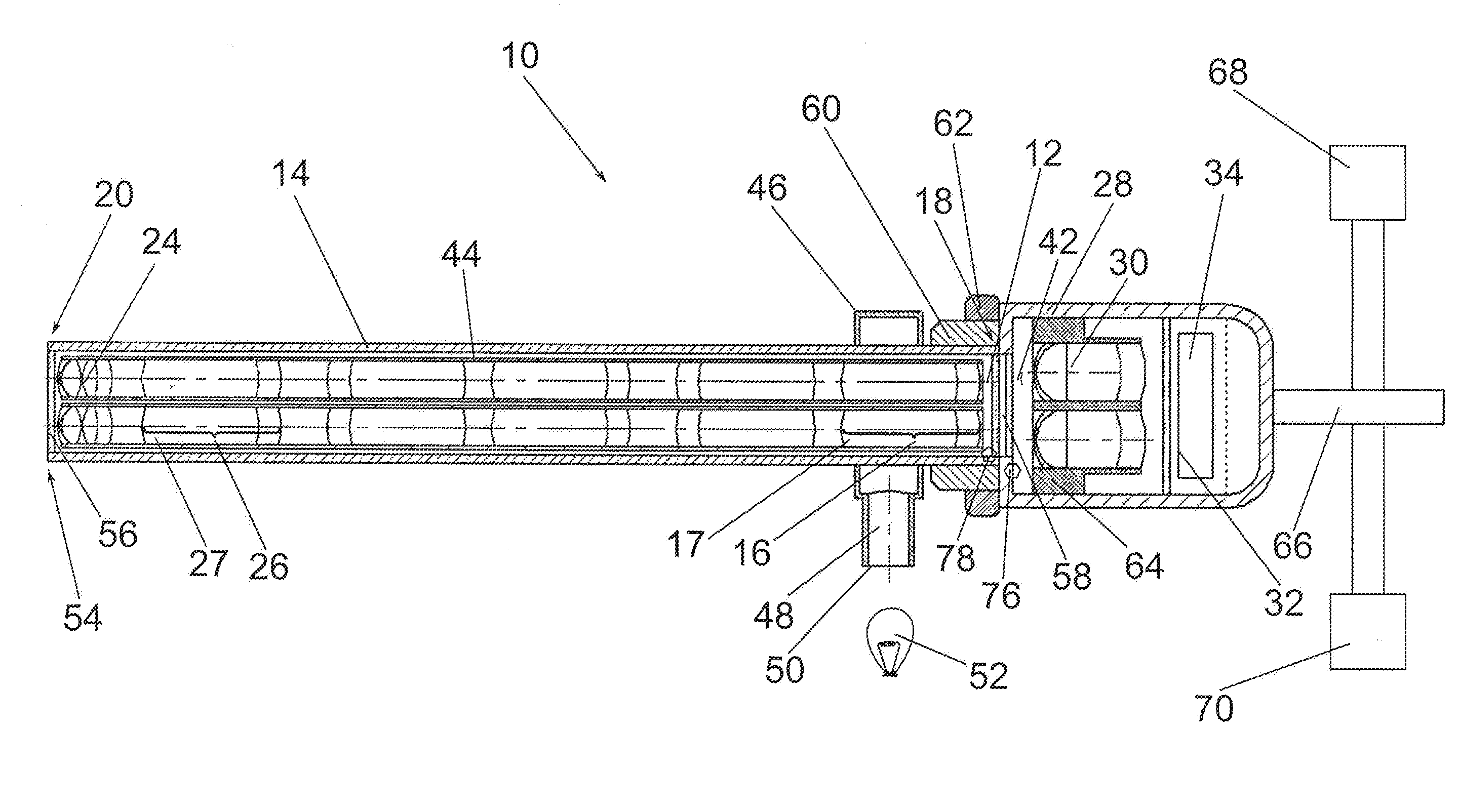
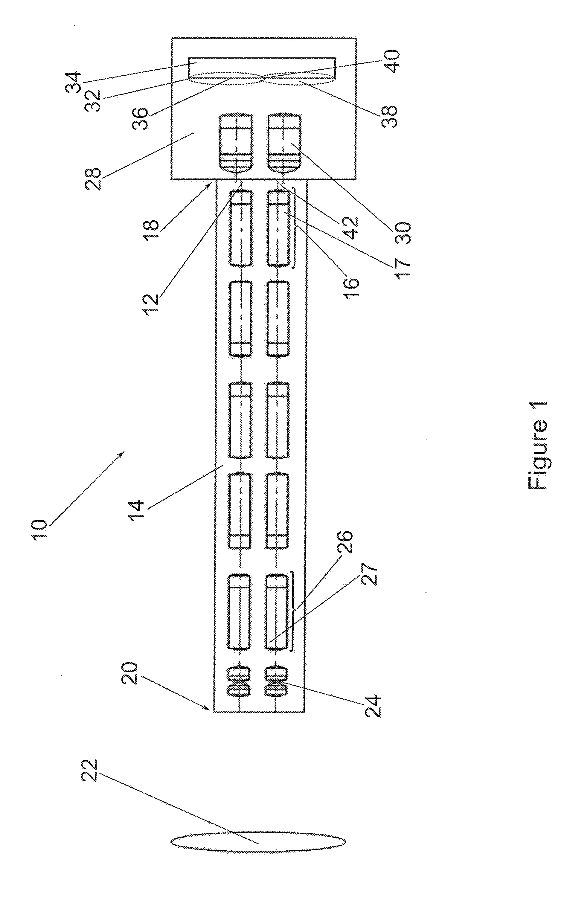
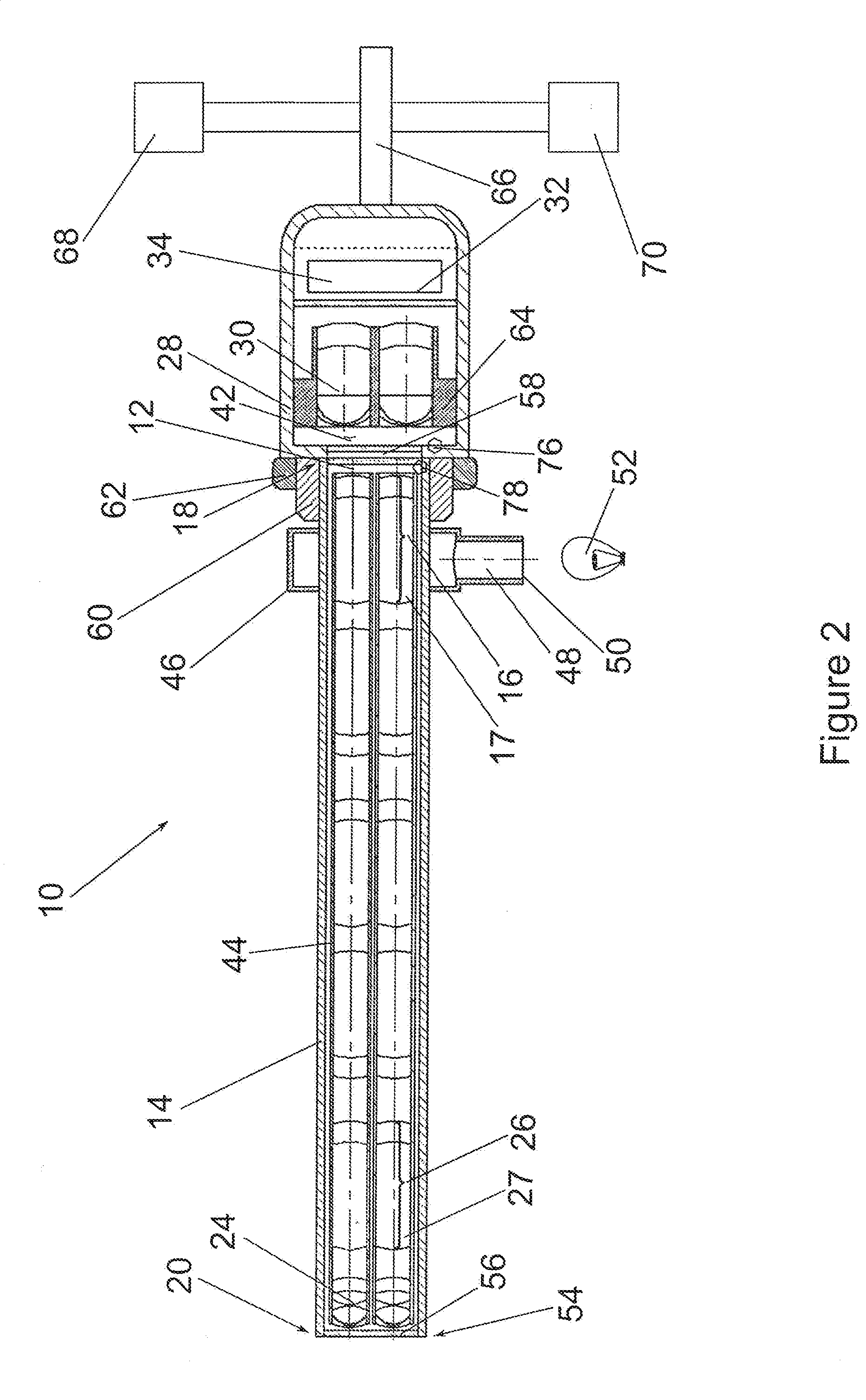
[0071]FIG. 1 shows a schematic illustration of a first exemplary embodiment of a video endoscopic device 10 with two parallel beam paths 12 which extend through the interior of an endoscope shaft 14 and are collimated by a respective collimating rod lens system 16 at the proximal end 18 of the endoscope shaft 14.

[0072]An object 22 situated in front of the distal end 20 of the endoscope shaft 14 is imaged by means of two parallel objectives 24. The image generated near the distal end 20 of the endoscope shaft 14 by the objectives24 is transmitted, by means of two image guiding rod lens system arrangements which are arranged in parallel and made of a plurality of rod lens systems 26 arranged coaxially with one another, in the direction of the proximal end 18 of the endoscope shaft 14 and is collimated there by the collimating rod lens systems 16. The rod lens systems 16, 26 can consist of cemented rod lenses 17, 27 and / or of other lenses cemented therewith.

[0073]The proximal end 18 of...


PUM


Abstract

A video endoscopic device has a camera head and two parallel optical arrangements, each with optical components, arranged coaxially with one another along a common first optical axis of the optical components of a respective optical arrangement and in the interior of an endoscope shaft. The optical components transmit an optical image from a distal end of the respective optical arrangement to a proximal end of the respective optical arrangement. The camera head contains at least one image sensor comprising a recording plane and at least two projection objectives, each having a second optical axis and arranged to project an image onto the image sensor. The optical arrangements comprise a collimating optical unit for generating an at least approximately parallel beam path at the outlet of the respective optical arrangement. The respective collimating optical unit has a third optical axis arranged coaxially with the optical components of the optical arrangements.

Description

CROSS REFERENCE TO RELATED APPLICATION[0001]This application claims priority under 35 USC §119 to German Patent Application No. 102013209956.8 filed on May 28, 2013, which application is hereby incorporated by reference in its entirety.TECHNICAL FIELD[0002]The invention relates to a video endoscopic device, comprising an endoscope shaft and a camera head, in which two separate stereoscopic partial images are projected onto a common image sensor or two image sensors. These partial images can be converted into a stereoscopic image by means of an image processor and depicted on a stereoscopic screen.BACKGROUND OF THE INVENTION[0003]Conventionally, stereoscopic surgical microscopes are used during surgery. In minimally invasive surgery, these instruments cannot be used and the operating medical practitioner can observe the operating site situated in a body opening only by means of an endoscope or other special aids. When performing such operations, stereo endoscopes provide additional d...

Claims


Application Information

Patent Timeline
Patent Type & Authority Applications(United States)
IPC IPC(8): A61B1/00A61B1/06A61B1/055
CPCA61B1/00009A61B1/00045A61B1/06A61B1/055G02B23/2415G02B23/2446H04N13/218H04N2213/001A61B1/00193A61B1/042H04N23/555A61B17/00A61B1/000095A61B1/0625A61B1/05
Inventor MULLER, HOLGERKLIEM, ALEXANDER
Owner XION
Why Eureka
Try Eureka