
System and Method for Reducing Reactive Current on a Common DC Bus with Multiple Inverters

a reactive current and dc bus technology, applied in the direction of dc network circuit arrangement, two-wire dc circuit arrangement, etc., can solve the problems of high frequency switching generating undesirable reactive currents at carrier frequency and harmonics, significant increase in cost and potentially undesirable weight of the controlled system, and achieve the effect of reducing the total reactive current presen

Active Publication Date: 2014-12-11
ROCKWELL AUTOMATION TECH
View PDF6 Cites 26 Cited by
  • Summary
  • Abstract
  • Description
  • Claims
  • Application Information

AI Technical Summary

Benefits of technology

This patent describes a system that reduces the unwanted electrical currents in a system with multiple inverters. The system uses processors or synchronizing signals to coordinate the timing of the inverters and reduce the overlap of their currents. The system also analyzes the carrier signals of each inverter to determine the starting point of the current flow period. By adjusting the starting points of the currents, the system can cancel out the negating effects of one inverter's current on another, resulting in a net reduction of the overall current in the system.

Problems solved by technology

However, the high frequency switching generates undesirable reactive currents at the carrier frequency and harmonics, or multiples, thereof, which may be present, for example, on the DC bus.
An increase in the wire gauge or other DC link components results in a significant increase in cost and potentially undesirable weight to the controlled system.

Method used


Image

  • System and Method for Reducing Reactive Current on a Common DC Bus with Multiple Inverters
  • System and Method for Reducing Reactive Current on a Common DC Bus with Multiple Inverters
  • System and Method for Reducing Reactive Current on a Common DC Bus with Multiple Inverters

Examples


Embodiment Construction

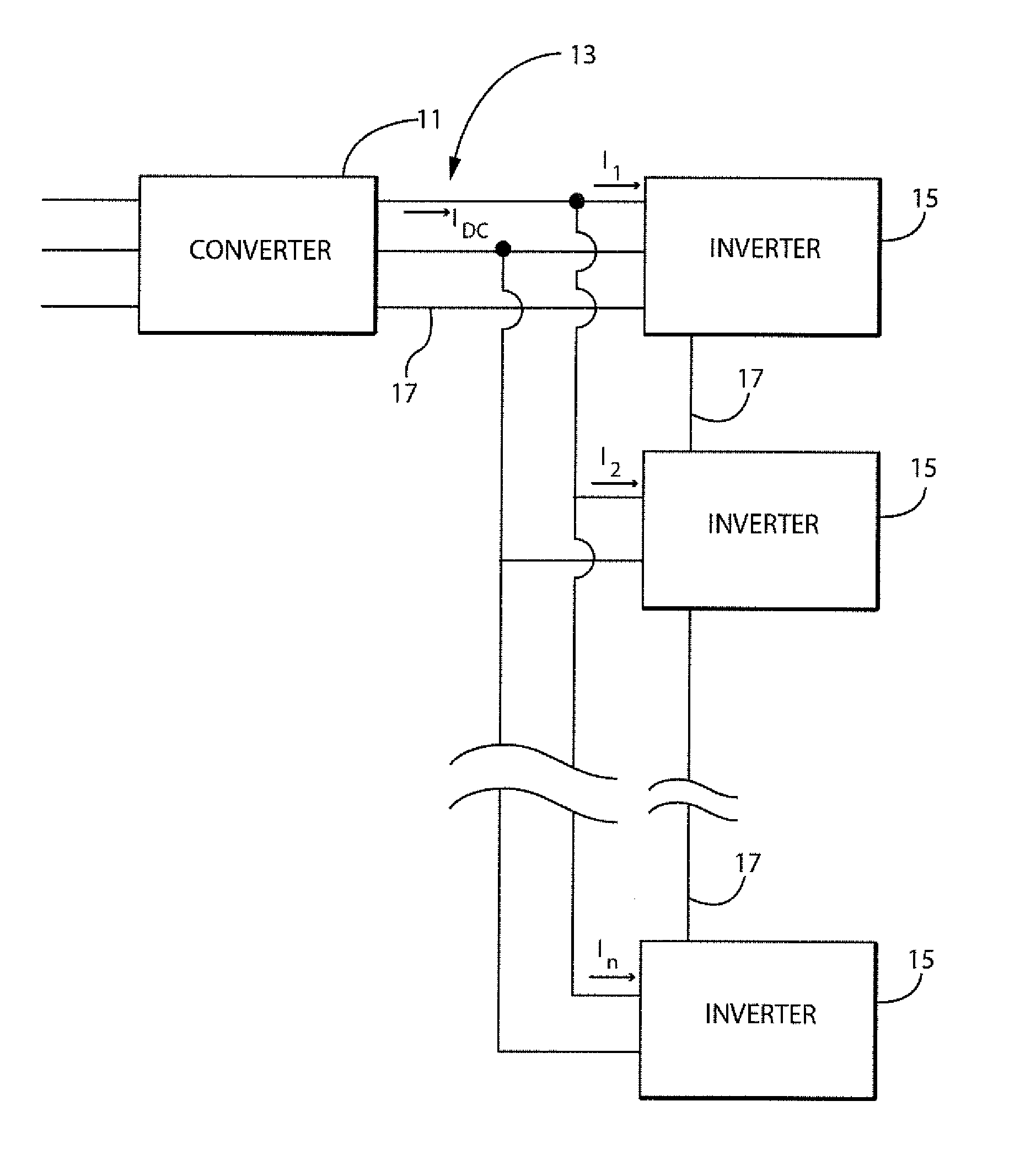
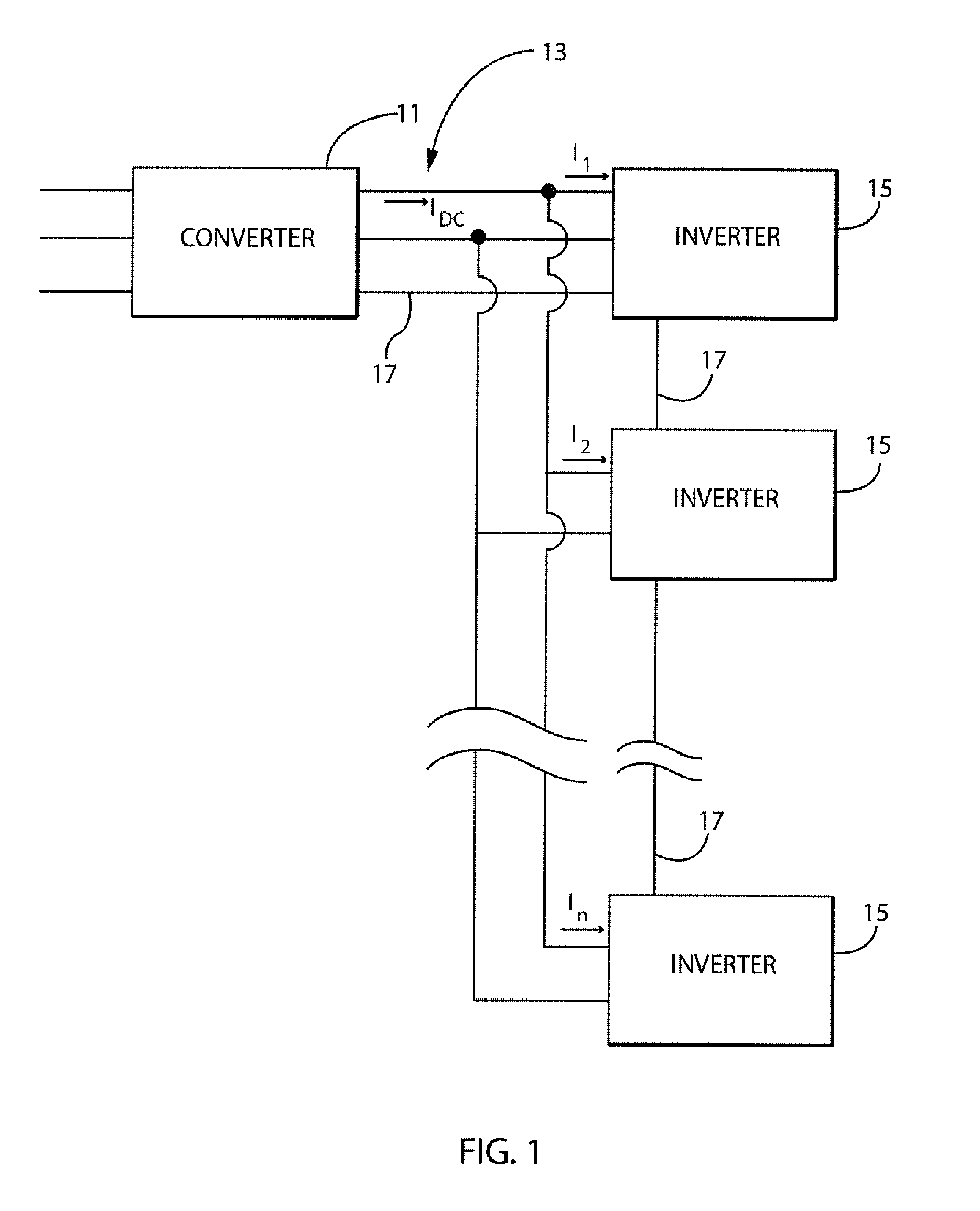
[0034]Turning initially to FIG. 1, a block diagram representation of a system including multiple inverters 15 connected to a single DC bus 13 is illustrated. According to the illustrated embodiment, a converter 11 receives power in a first form and provides it to the DC bus 13. The input may be a DC voltage or an AC voltage, where the AC voltage is either single phase or multi-phase. The converter 11 is configured to supply a regulated DC voltage on the DC bus 13. The system includes at least a first inverter 15 and a second inverter 15, but may include any number of additional inverters 15. Each inverter 15 converts the DC voltage present on the DC bus 13 to an AC voltage for use by an electrical load. Communication media 17 extends between the converter 11 and each inverter 15. The communication media 17 may be a single electrical conductor, multiple electrical conductors, a network cable configured to transmit data packets, or any other suitable communication media 17 configured ...


PUM


Abstract

A system configured to reduce the amplitude of reactive current present on a DC bus shared by multiple inverters is disclosed. The start of the switching period for the modulation routines of each inverter is synchronized, and a carrier phase angle is determined for a carrier signal within each of the inverters. The modulation routine of each inverter generates a reactive current on the shared DC bus. By controlling the carrier phase angle for each inverter, the reactive current of a first inverter may be generated at a phase angle that is offset from the phase angle of the reactive current generated by a second inverter. As a result, the reactive current from the first inverter cancels at least a portion of the reactive current from the second inverter, reducing the total reactive current present on the DC bus.

Description

BACKGROUND OF THE INVENTION[0001]The subject matter disclosed herein relates generally to a system having a direct current (DC) bus which is shared by multiple inverters and, more specifically, to a system for reducing the amplitude of reactive current present on the DC bus as a result of the multiple inverters.[0002]As is known to those skilled in the art, a motor drive receives an input voltage and converts the input voltage to a suitable output voltage for controlling operation of a motor. In an Alternating Current (AC) motor drive, a three phase AC voltage is typically available at, for example, 230 V or 460 V as the input voltage. The motor drive includes a converter section that rectifies the AC input voltage into a Direct Current (DC) voltage. The DC voltage is present across a first rail and a second rail of a DC bus in the motor drive. An inverter section includes switches, such as transistors, thyristors, or silicon-controlled rectifiers to convert the DC voltage on the DC...

Claims


Application Information

Patent Timeline
IPC IPC(8): H02J1/06
CPCH02J1/06H02M1/14H02M7/493H02M1/008H02M1/0043
Inventor HUANG, RONGJUNWINTERHALTER, CRAIGGRIES, MARKLI, YE
Owner ROCKWELL AUTOMATION TECH
Learn More