
Resolver excitation apparatus

Active Publication Date: 2014-12-11
AISIN AW CO LTD
View PDF6 Cites 12 Cited by
  • Summary
  • Abstract
  • Description
  • Claims
  • Application Information

AI Technical Summary

Benefits of technology

The patent describes a resolver excitation apparatus that reduces loss and can be flexibly applied to a wide range of power supply voltage. The apparatus uses both a parallel resonant circuit and a series resonant circuit to generate the excitation signal. By optimizing the power supply voltage and using a low-loss circuit configuration, the apparatus can provide a sinusoidal excitation signal with required amplitude for excitation. The apparatus also includes a feedback controller and a band-pass filter to stabilize the amplitude of the excitation signal and filter out high-frequency components. Overall, the apparatus reduces loss, is flexible, and provides an efficient solution for excitation in a variety of applications.

Problems solved by technology

Accordingly, it is not practically easy to flexibly and appropriately set the frequency of the excitation signal as in Patent Document 1.
However, loss of the circuit tends to increase with an increase in power supply voltage.
The loss is small if the excitation apparatus includes a power supply having a power supply voltage value optimal for the excitation apparatus, but otherwise the loss may increase.
For example, if the voltage value of the power supply included in the excitation apparatus is higher than the optimal power supply voltage value, the loss is greater as the power supply voltage value is higher.
If the voltage value of the power supply included in the excitation apparatus is lower than the optimal power supply voltage value, the excitation apparatus cannot provide a sinusoidal output having required amplitude, and provides an output having a waveform distorted with respect to the sinusoidal waveform.

Method used


Image

  • Resolver excitation apparatus
  • Resolver excitation apparatus
  • Resolver excitation apparatus

Examples


Embodiment Construction

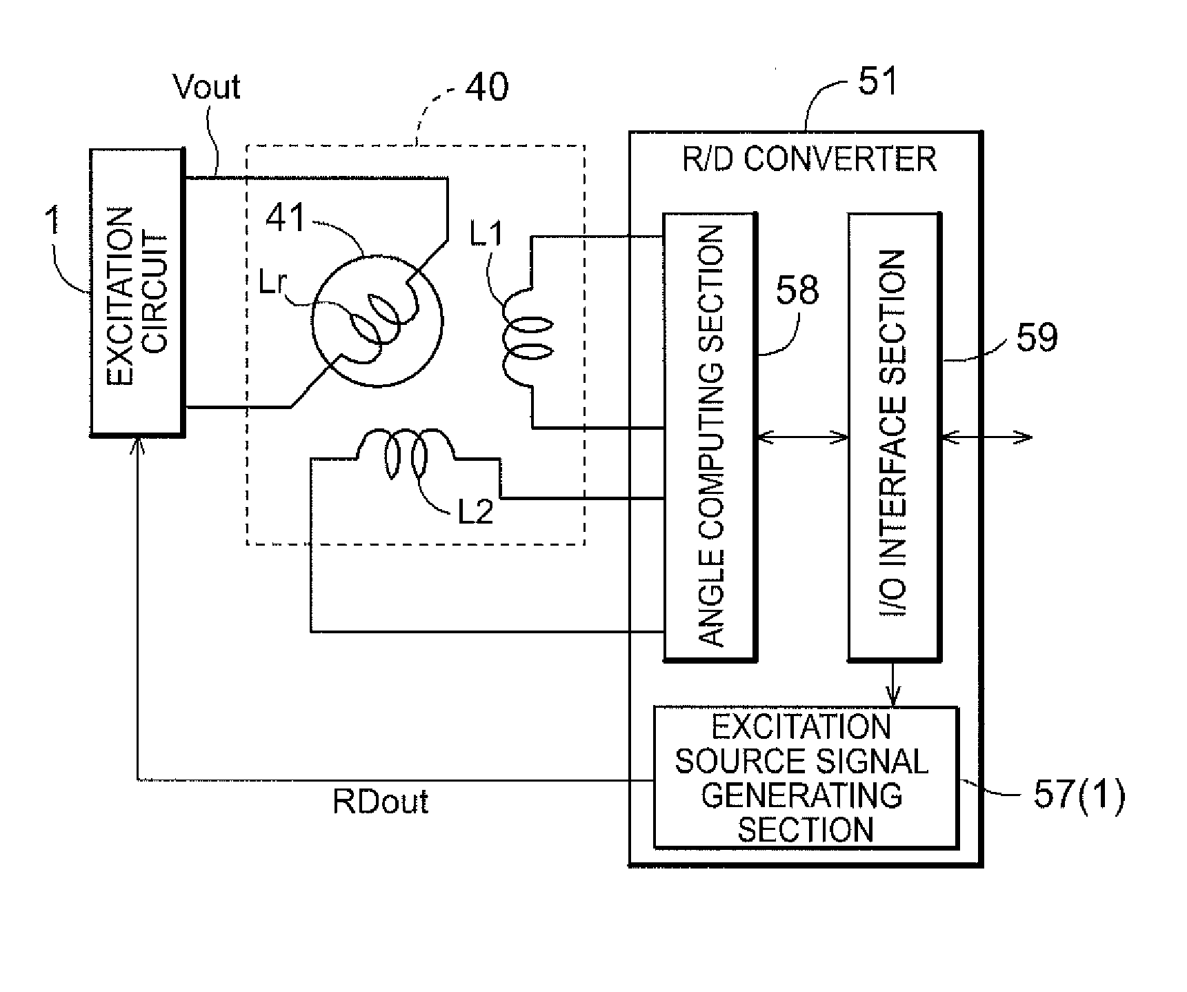
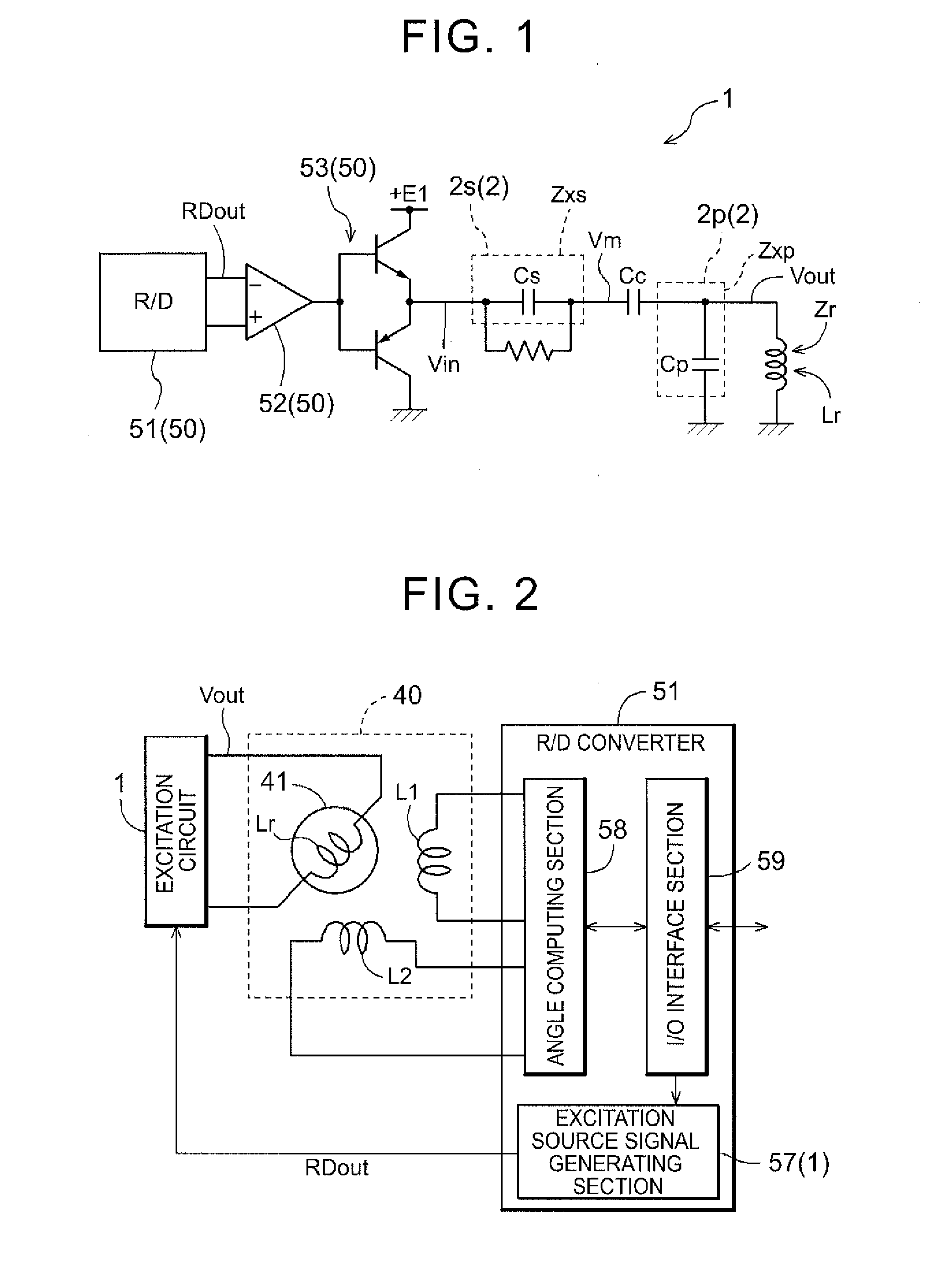
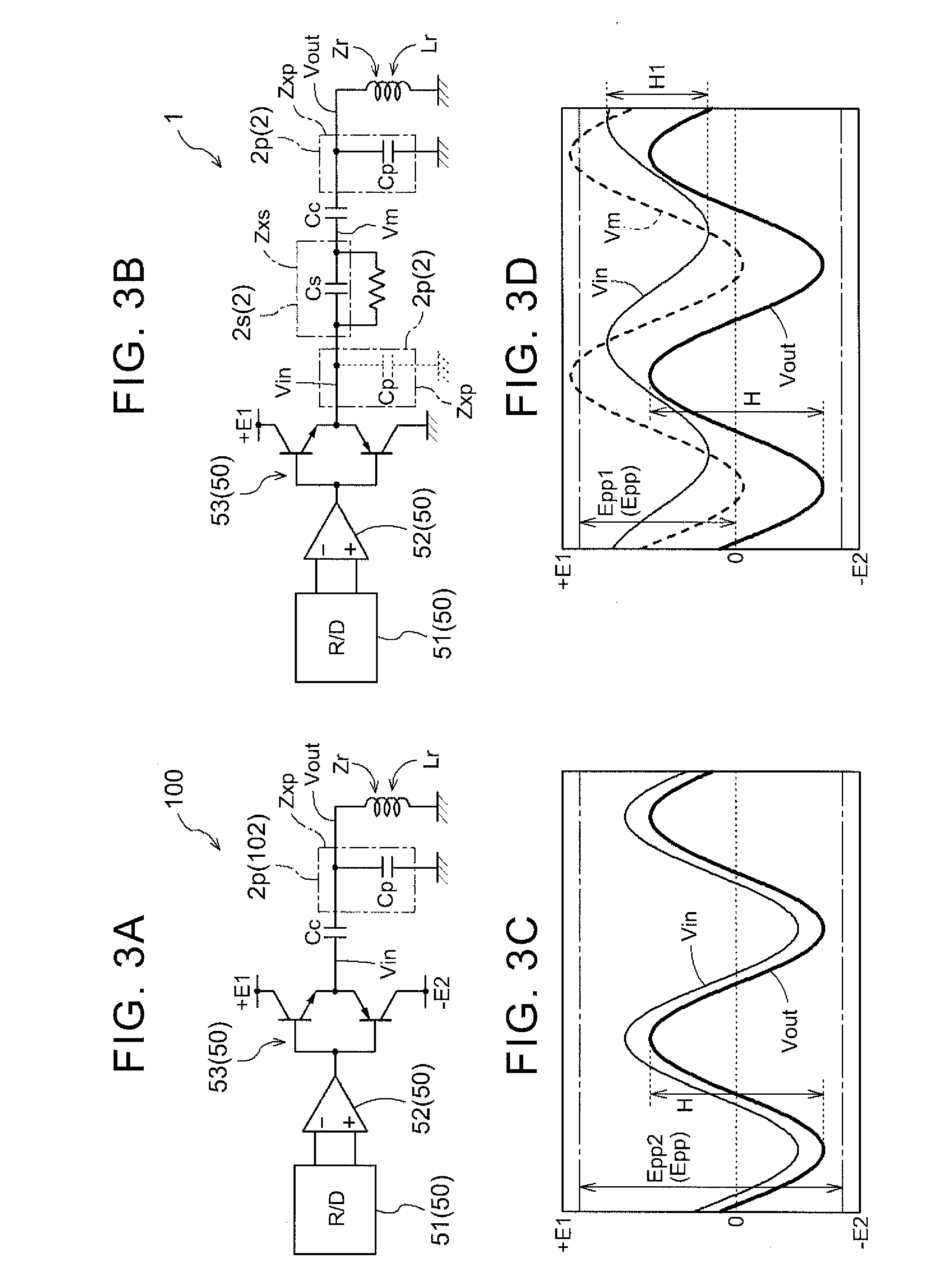
[0061]Excitation circuits that are applied to a resolver excitation apparatus according to the present invention are shown by way of example with reference to the accompanying drawings to describe embodiments of the present invention. The schematic circuit diagram of FIG. 1 shows an excitation circuit 1 illustrating the subject matter of the present invention. The block diagram of FIG. 2 shows the relation among the excitation circuit 1, a resolver 40, and a resolver / digital converter (RID converter) 51 described below. In order to excite an excitation winding Lr of the resolver 40, the excitation circuit 1 (resolver excitation apparatus) adjusts the amplitude of a sinusoidal excitation source signal RDout to generate an excitation signal Vout having predetermined amplitude (e.g., corresponding to one half of a peak value “H” shown in FIG. 3). This excitation circuit 1 has: an excitation source signal supply section 50 having the RID converter 51 that outputs the excitation source s...


PUM


Abstract

A resolver excitation apparatus that adjusts amplitude of a sinusoidal excitation source signal to generate an excitation signal having predetermined amplitude in order to excite an exciting winding of a resolver. A parallel resonant circuit having a parallel resonant element that functions as parallel resonant impedance for impedance of the excitation winding. A series resonant circuit having a series resonant element that functions as series resonant impedance for the impedance of the excitation winding.

Description

TECHNICAL FIELD[0001]The present invention relates to resolver excitation apparatuses that adjust the amplitude of a sinusoidal excitation source signal to generate an excitation signal having a predetermined amplitude in order to excite an excitation winding of a resolver.BACKGROUND ART[0002]Resolvers are sometimes used as a rotation detection sensor that detects rotation (the rotational speed or rotational position (angle of rotation) of a rotor) of a rotating electrical machine. The resolvers typically have an excitation winding on the stator side, and detect rotation of the rotating electrical machine based on a principle that the angle of rotation of a rotor is detected according to an output voltage induced to an output winding provided on the rotor side. Accordingly, an alternating current (AC) signal is normally applied to the excitation winding. An excitation apparatus that applies this AC signal has a sinusoidal oscillator circuit that generates a sinusoidal oscillation si...

Claims


Application Information

Patent Timeline
IPC IPC(8): G01D5/20
CPCG01D5/20G01D5/2073
Inventor NAKAMURA, YASUSHI
Owner AISIN AW CO LTD
Learn More