Contactless user interface

a user interface and contactless technology, applied in the field of user interface devices, can solve the problems of affecting the contact with the user's fingers tends to quickly get dirty, and the operation of the touch surface is generally degraded, so as to achieve the effect of convenient manufactur

Inactive Publication Date: 2014-12-11
ISORG +1
View PDF5 Cites 11 Cited by
  • Summary
  • Abstract
  • Description
  • Claims
  • Application Information

AI Technical Summary

Benefits of technology

[0013]Thus, an object of an embodiment of the present invention is to provide a user interface device overcoming at least some of the disadvantages of existing devices.
[0015]Another object of an embodiment of the present invention is to provide a contactless user interface device capable of operating without emitting any radiation.
[0017]Another object of an embodiment of the present invention is to provide a user interface device which is easier to manufacture than existing devices.
[0018]Another object of an embodiment of the present invention is to provide a user interface device capable of being formed on a greater variety of supports than current devices, and particularly on low-cost supports such as plastic, paper, fabric, etc.

Problems solved by technology

A disadvantage of this type of interface is that the contact with the users' fingers tends to rapidly get the touch surface dirty.
Touch surfaces further raise a hygiene issue, in particular in hospitals where they may be a disease transmission vector.
Further, the operation of touch surfaces is generally degraded when the user is wearing gloves.
This may be a problem in certain fields of application (industry, surgery, outdoor use by cold weather, ticket vending machines for ski resorts, etc.).
A disadvantage of this type of device is that the emission of the infrared radiation by the proximity sensors causes an unwanted power overconsumption.
Further, touch surfaces, touch screens, and proximity sensors of the above-mentioned type are relatively complex to form.
The forming of organic semiconductor components however remains rather complex.
In particular, it is necessary to provide low-pressure vapor deposition phases and anneal phases at relatively high temperatures, for example, higher than 250° C. As a result, such components can only be formed of particularly robust supports, and by means of relatively expensive equipment.
Further, the juxtaposing of such components on large surface areas is difficult since it is difficult (or too expensive) for deposition equipment to treat supports of large dimensions (for example, having a diameter greater than 30 cm).

Method used


Image

  • Contactless user interface
  • Contactless user interface
  • Contactless user interface

Examples


Embodiment Construction

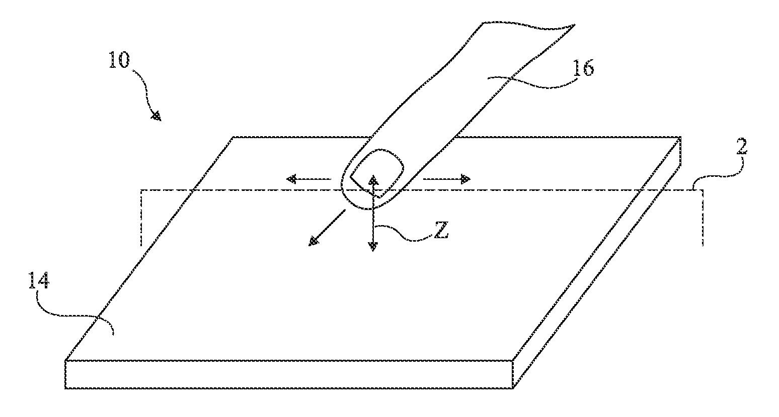
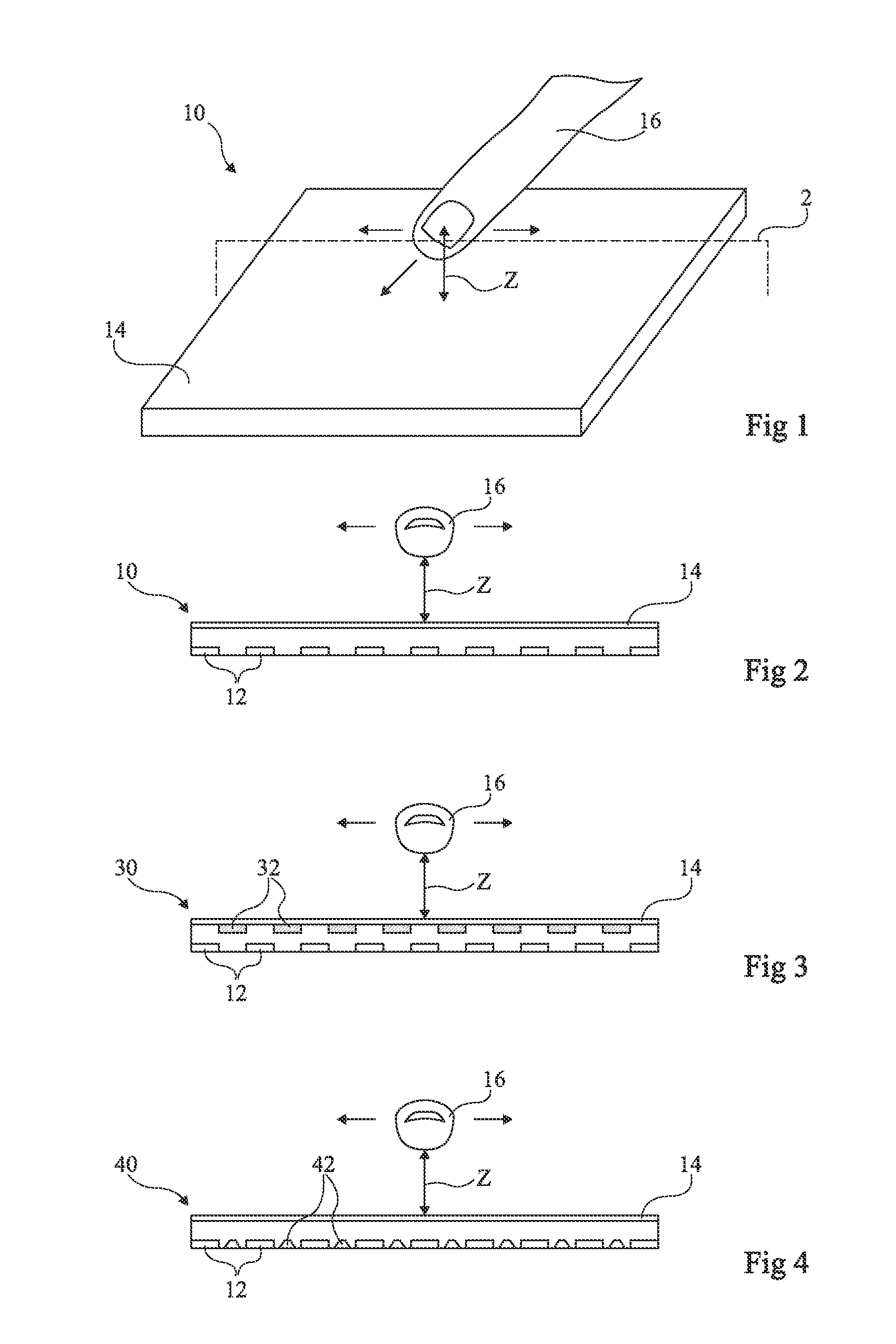
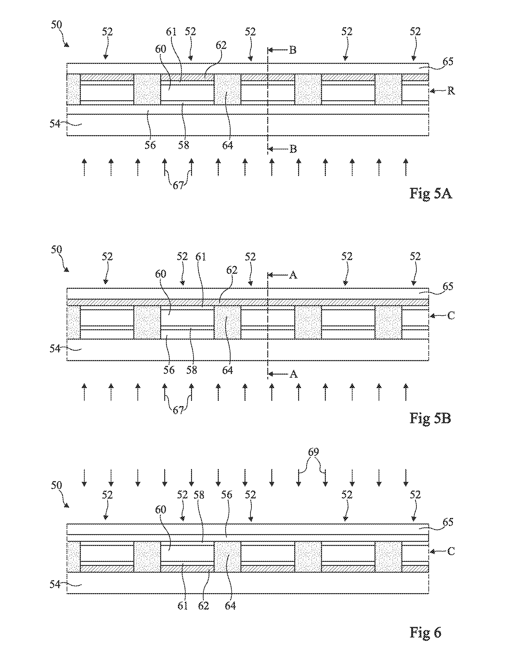
[0044]For clarity, the same elements have been designated with the same reference numerals in the various drawings and, further, as usual in the representation of integrated circuits, the various drawings are not to scale. Further, only those elements which are useful to the understanding of the present invention have been shown and will be described. In particular, what use is made of the user interface devices described hereafter has not been detailed. It will be within the abilities of those skilled in the art to use the provided devices in any type of system capable of being controlled via a touch and / or contactless interface. Further, the means for processing the information provided by the user interface devices described hereafter and the means of connection with the system(s) to be controlled are within the abilities of those skilled in the art and will not be described.

[0045]A first aspect of an embodiment of the present invention provides a user interface device capable of...


PUM


Abstract

The invention relates to a user interface device (10) comprising a matrix of photon sensors (12), adapted for detecting variations in the shadow of an actuation member (16) and for deducing therefrom an item of information representative of a variation of position of the actuation member.

Description

BACKGROUND[0001]The present disclosure relates to a user interface device, or man-machine interface.DISCUSSION OF THE RELATED ART[0002]User interface devices controllable by simple sliding of a finger or of the hand on a touch-sensitive surface, or touch surface, have already been provided. The touch surface may be superimposed over a display, which enables to form an interactive user interface, or touch screen.[0003]Touch screens and surfaces are currently used in many fields. As an example, they have already been used to control cell phones, computers, television sets, motor vehicles, ticket vending machines, industrial equipment, medical equipment, etc.[0004]A disadvantage of this type of interface is that the contact with the users' fingers tends to rapidly get the touch surface dirty. This implies the necessity to provide a regular cleaning, in particular in case of use in dirty environments (factories, public transports, etc.). Touch surfaces further raise a hygiene issue, in ...

Claims


Application Information

Patent Timeline
Patent Type & Authority Applications(United States)
IPC IPC(8): G06F3/042
CPCG06F2203/04108G06F3/0421G06F3/042G06F2203/04101G06F2203/04102G06F2203/04103G06F2203/04104G06F2203/04106
Inventor GOMEZ, JEAN-YVESJAMET, LAURENTGUERINEAU, EMMANUELPREMONT, CHRISTOPHE
Owner ISORG
Why Eureka
Try Eureka