Coupled scaffold segments

a scaffold and segment technology, applied in the field of bioresorbable scaffolds, can solve the problems of high stress, several complexities, external forces applied by the peripheral-vessel's implant environment, etc., and achieve the effects of reducing fatigue life, reducing fatigue life, and reducing the loading of ring elements

Inactive Publication Date: 2014-12-11
ABBOTT CARDIOVASCULAR
View PDF14 Cites 42 Cited by
  • Summary
  • Abstract
  • Description
  • Claims
  • Application Information

AI Technical Summary

Benefits of technology

[0020]In particular, for scaffolds greater than 40 or 50 mm in length non-radial or non-pulsatile loading can be significant; indeed, it can be a major factor in reduced fatigue life for a scaffold implanted within a peripheral vessel. One approach to addressing the reduced fatigue life is to decouple portions of the scaffold. Tha

Problems solved by technology

The external forces applied by the peripheral-vessel's implant environment are believed to produce high stresses, in large part due to the presence of axial load paths between adjacent ring elements.
While this a

Method used


Image

  • Coupled scaffold segments
  • Coupled scaffold segments
  • Coupled scaffold segments

Examples


first embodiment

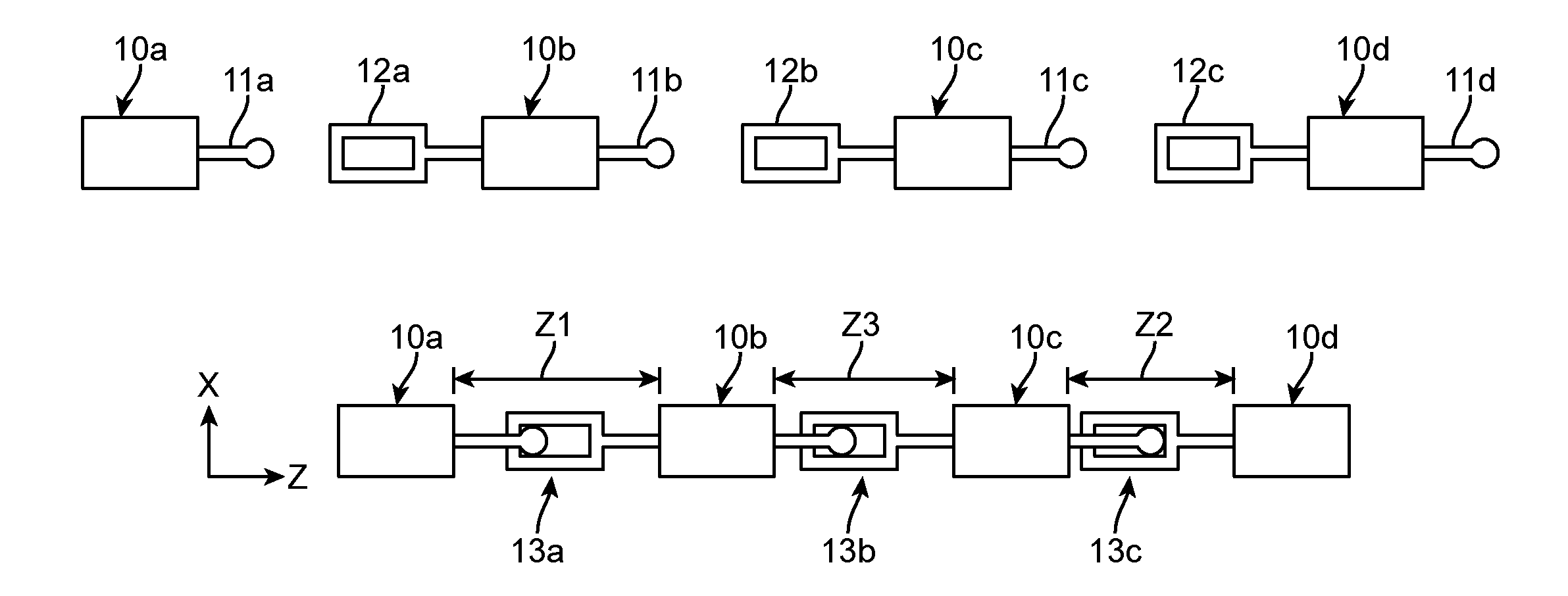
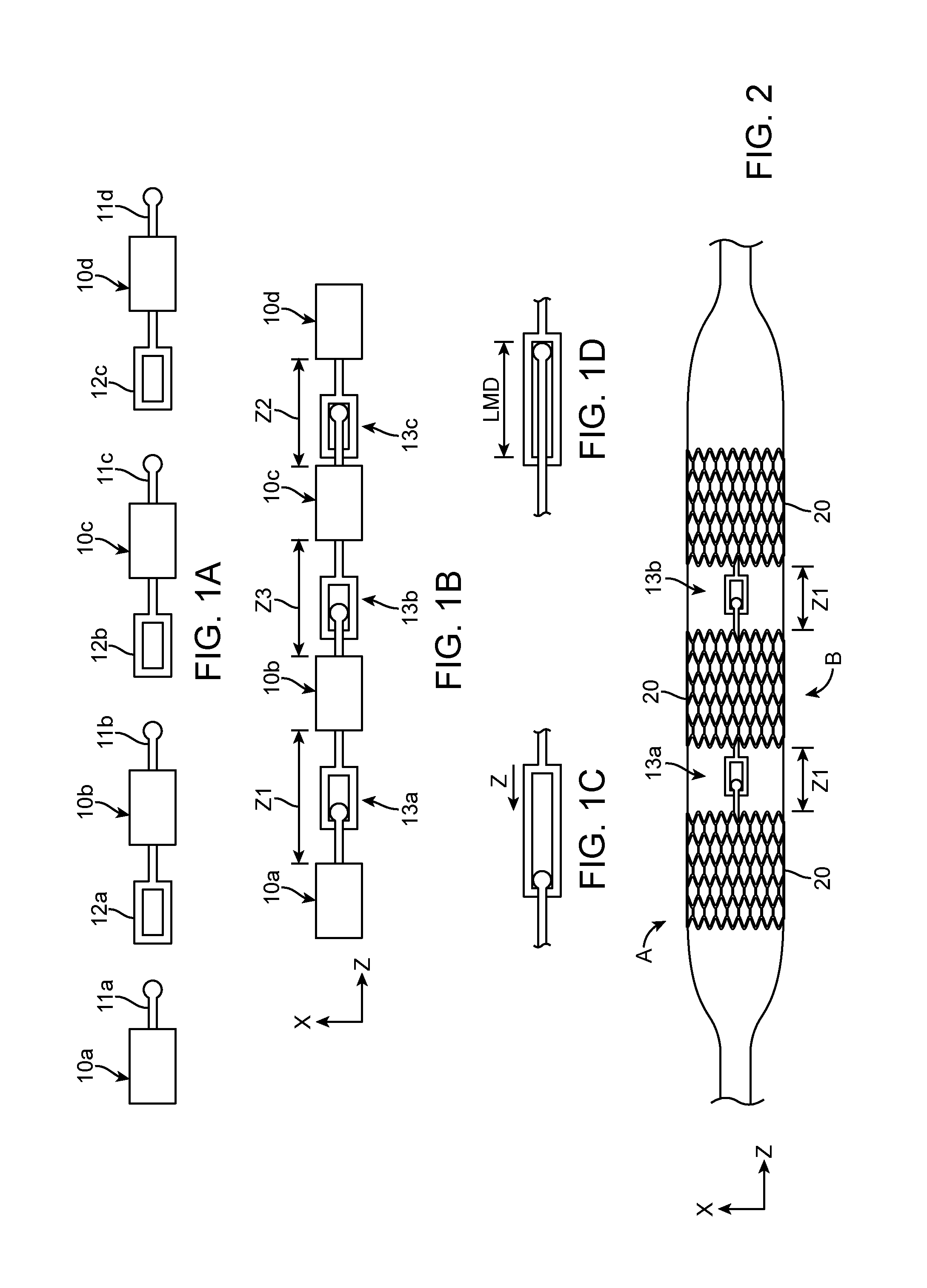
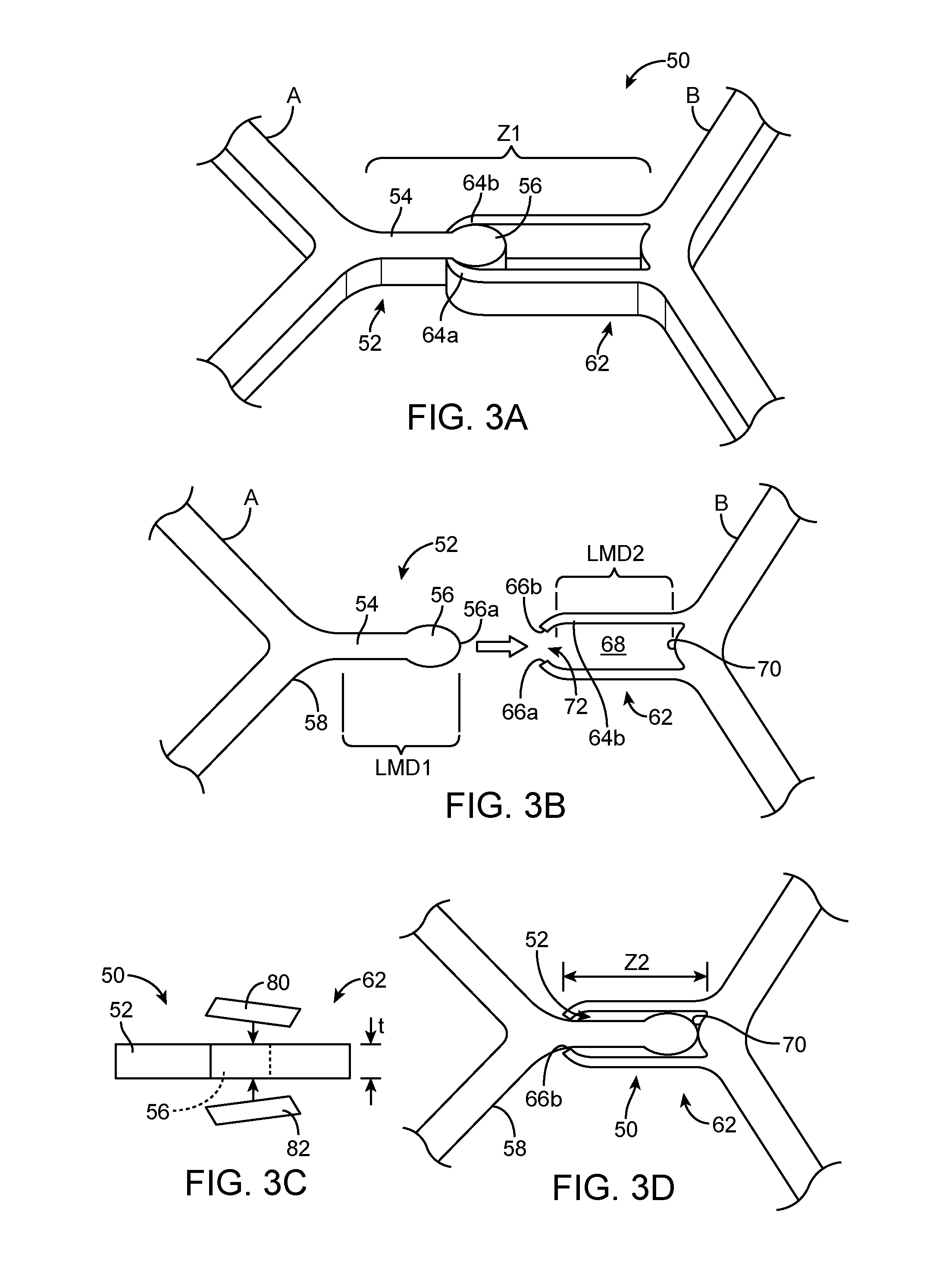
[0102]FIGS. 3A-3D depict aspects of a coupling, which may be regarded as a ball and socket type coupling according to the disclosure. The coupling 50 includes a pin or male portion 52 and a slot female portion 62. The male and female portions 52, 62 are formed integrally with the respective segments A and B, as illustrated. Additionally, a rivet, pin or cover, illustrated schematically as top and bottom covers, pieces or heads 80, 82 welded or glued to the inner and outer surfaces of the female portion 62 to retain the male portion within the female slot 68 during movement of the segment A or B. As such, there is only Z translation permitted between segment A and segment B. Specifically, when the segments A and B are spaced by Z1, FIG. 3A, they may only freely translate towards each other. And when the segments A and B are spaced by Z2, FIG. 3D, they may only freely translate away from each other.

[0103]The DOF of the joint defined by coupling 50 is Z translation only.

[0104]The Z1 di...

second embodiment

[0108]FIGS. 4A-4D depict aspects of a coupling, which may be regarded as a flexible coupling or hook and loop coupling according to the disclosure. The coupling 100 includes identical arms 102, 112 forming hooks 114a and 114b configured to receive a flexible band 106. FIGS. 4C and 4D show the fully assembled coupling 100. FIG. 4A shows the coupling 100 less the flexible band 106. Referring to FIG. 4B the hook 114 may include an edge 116 configured to deflect outwardly about a living hinge 118 formed as a narrowed portion of the material, as illustrated. The flexible band 106 may then be slipped into the space 118 where it is retained. The flexible band 106 may be made of a bioresorbable elastomer, e.g., a “rubber band” or a flexible bioresorbable polymer. The segment is made from a first polymer and the band is made from a second polymer, wherein the second polymer has a material stiffness that is substantially less than (i.e., by a factor of 2, 5, 10) and / or elongation to break tha...


PUM


Abstract

A scaffold is formed by several segments joined or connected to each other by only at least one coupling. The coupling decouples the segments in the axial direction over a finite distance of axial displacement. The scaffold when implanted in a peripheral vessel reduces loading on rings of a segment due to the decoupling of the segments in the axial direction over the finite distance.

Description

BACKGROUND OF THE INVENTION[0001]1. Field of the Invention[0002]The present invention relates to bioresorbable scaffolds; more particularly, this invention relates to bioresorbable scaffolds for treating peripheral vessels of the body.[0003]2. Description of the State of the Art[0004]Radially expandable endoprostheses are artificial devices adapted to be implanted in an anatomical lumen. An “anatomical lumen” refers to a cavity, duct, of a tubular organ such as a blood vessel, urinary tract, and bile duct. Stents are examples of endoprostheses that are generally cylindrical in shape and function to hold open and sometimes expand a segment of an anatomical lumen (one example of a stent is found in U.S. Pat. No. 6,066,167 to Lau et al). Stents are often used in the treatment of atherosclerotic stenosis in blood vessels. “Stenosis” refers to a narrowing or constriction of the diameter of a bodily passage or orifice. In such treatments, stents reinforce the walls of the blood vessel and...

Claims


Application Information

Patent Timeline
IPC IPC(8): A61F2/07
CPCA61F2/07
Inventor ELI, ERIK DAVIDHOSSAINY, SYEDTROLLSAS, MIKAELNGO, MICHAEL H.PACETTI, STEPHENGREEN, MICHAELPAPP, JOHN
Owner ABBOTT CARDIOVASCULAR
Why Eureka
Try Eureka