Systems and methods for separating alkane gases with applications to raw natural gas processing and flare gas capture

a technology of raw natural gas processing and separation methods, applied in the direction of lighting and heating equipment, instruments, computer control, etc., can solve the problems of high vapor pressure and inability to transport in existing propane tanks, and achieve the effect of reducing the operating pressure of the entire system, high quality separation, and optimizing temperature and pressure rang

Inactive Publication Date: 2014-12-18
PIONEER ENERGY
View PDF28 Cites 59 Cited by
  • Summary
  • Abstract
  • Description
  • Claims
  • Application Information

AI Technical Summary

Benefits of technology

[0014]The inventors have realized as a result of substantial experimental work that an optimal temperature and pressure range for the entire process can be achieved with a unique refrigeration design and unique overall system design. The result is a system that can achieve high-quality separation in a field environment using a mobile processing plant. By utilizing a unique cascade / autocascade refrigeration system to achieve an optimal temperature range, the inventors have been able to reduce the operating pressure of the entire system, as well as reduce the cost and complexity of the entire system. The result is a portable natural gas processing plant that can simultaneously achieve both lean methane separation as well as NGLs capture meeting Y-grade specification.

Problems solved by technology

Some existing solutions were designed for extracting NGLs from flare gas, and then flared the remaining methane and ethane because it was unusable in existing gensets.
Other existing solutions generated high-quality (lean) methane for CNG or pipelines, and flared the remaining NGLs because it had high ethane content, and hence a high vapor pressure, too high to be transportable in existing propane tanks.

Method used


Image

  • Systems and methods for separating alkane gases with applications to raw natural gas processing and flare gas capture
  • Systems and methods for separating alkane gases with applications to raw natural gas processing and flare gas capture
  • Systems and methods for separating alkane gases with applications to raw natural gas processing and flare gas capture

Examples


Embodiment Construction

[0043]The following description is merely exemplary in nature and is in no way intended to limit the scope of the present disclosure, application, or uses.

DEFINITIONS

[0044]The following terms of art shall have the below ascribed meanings throughout this specification, unless otherwise stated.

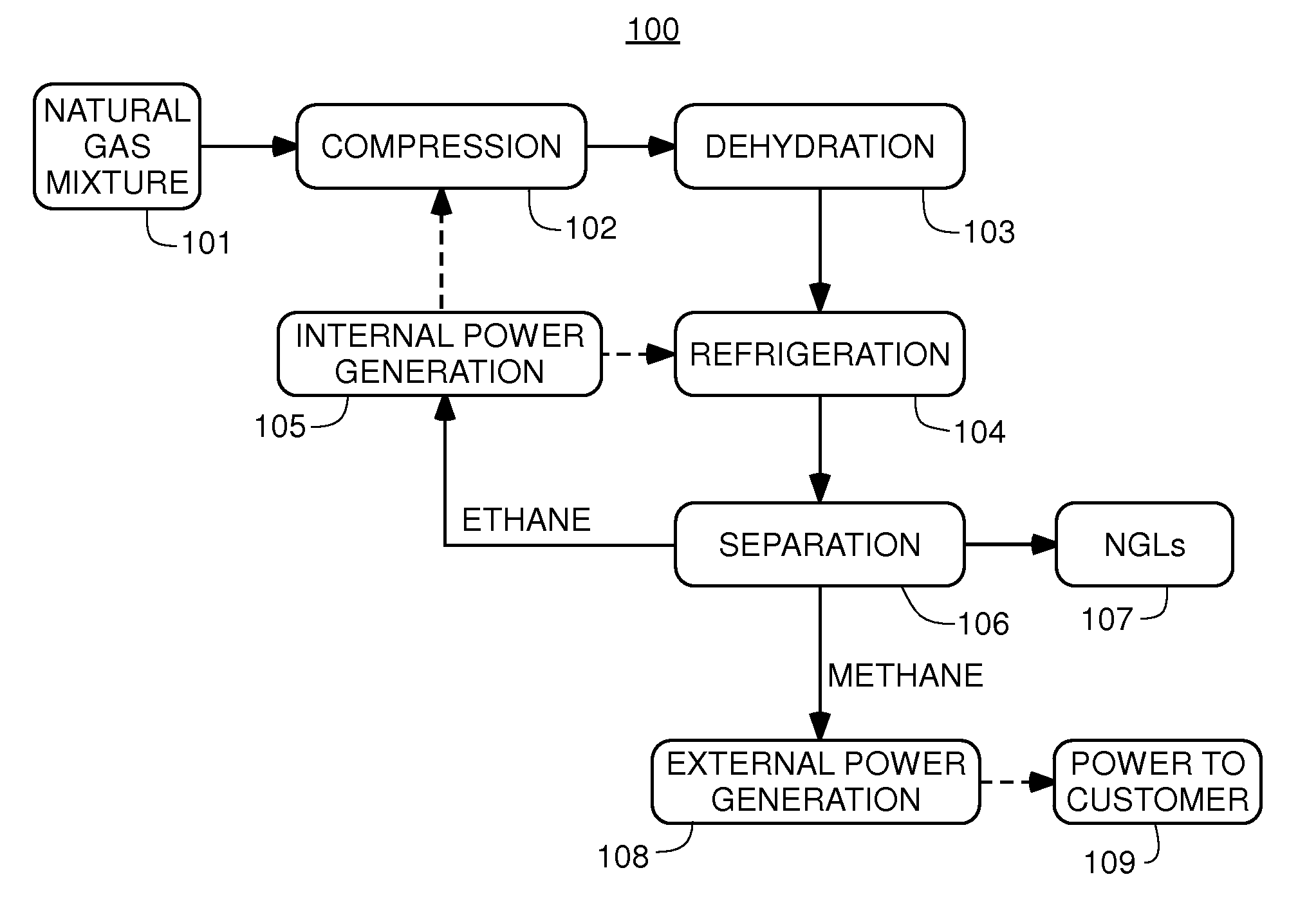
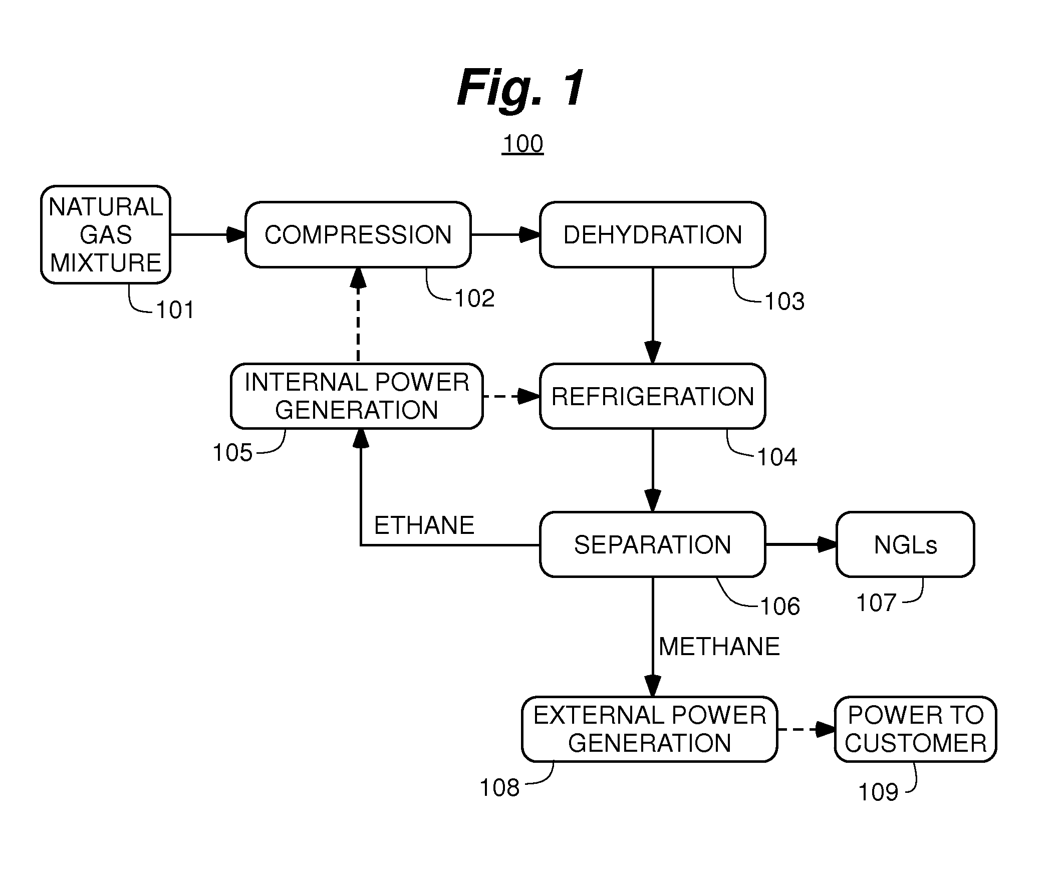
[0045]Throughout this disclosure “MAGS-200,”“full scale” apparatus, or any reference to a single full-scale module, will refer to an apparatus module that can process 200 mcf (thousand cubic feet) of raw natural gas per day. Assuming a typical Bakken gas composition illustrated in Table 1, the MAGS-200 unit would produce approximately 1700 gallons of natural gas liquids (˜46 mcf of gas equivalent, ˜23% of the total volume of flare gas), ˜100-120 mcf of lean methane (˜58% of the total volume of flare gas), and ˜25-40 mcf of an ethane-rich stream (˜19% of the total volume of flare gas). Multiple modules can be combined for higher gas flow rates. These product flow estimates are based on a sample a...


PUM


Abstract

The present invention is a field-deployable system for separating methane and natural gas liquids (NGLs) from a raw gas stream comprising a compressor; a dehydrator; a refrigerator having one or more stages; and a separation subsystem adapted to separate the raw gas stream into three product streams including a methane stream that is at least 80% methane, an ethane-rich stream, and a NGLs stream having a vapor pressure of no more than 250 psia at 38° C. The methane stream is sufficiently lean to be useable in existing natural gas engines without modification. The NGLs stream has a sufficiently low vapor pressure to be transportable in standard propane containers. The ethane-rich stream may be utilized within the system itself to power its own operations. The system can be utilized to reduce flaring from liquids-rich gas production sites to an absolute minimum, produce natural gas liquids for transport, and provide dry methane gas suitable for use in portable field generators.

Description

REFERENCE TO RELATED APPLICATIONS[0001]This application is a non-provisional of and claims priority from U.S. Ser. No. 61 / 836,220, filed on Jun. 18, 2013, entitled “Mobile Alkane Gas Separator,” the entirety of which is hereby incorporated by reference herein.FIELD OF THE INVENTION[0002]The present invention relates to enabling the utilization of raw natural gas, such as flare gas, for power generation and liquids capture. More specifically, this invention relates to a mobile system for separating raw natural gas into a high-quality methane gas stream, an ethane-rich gas stream, and a natural gas liquids stream having a low vapor pressure.BACKGROUND OF THE INVENTION[0003]The statements in this section merely provide background information related to the present disclosure and may not constitute prior art.[0004]Currently liquids-rich raw natural gas is being flared in large quantities at numerous locations by oil producers. This activity entails significant loss of income that could ...

Claims


Application Information

Patent Timeline
Patent Type & Authority Applications(United States)
IPC IPC(8): F25J3/08
CPCF25J3/08C10G5/06C10L3/101C10L3/106F25J3/0209F25J3/0233F25J3/0238F25J3/0242F25J2200/02F25J2200/70F25J2205/04F25J2205/60F25J2205/66F25J2205/70F25J2215/62F25J2220/68F25J2230/22F25J2230/30F25J2240/80F25J2260/60F25J2270/12F25J2270/18F25J2270/60F25J2270/66F25J2290/42F25J2290/70H04W76/10C10L3/10C10L2290/30C10L2290/46C10L2290/567C10L2290/58C10L2290/60G05B15/02
Inventor ZUBRIN, ROBERT MSARGSYAN, GEVORGHOTTON, KEVINLEWIS, MATTHEWYOUNG, ANDREW
Owner PIONEER ENERGY
Why Eureka
Try Eureka