Actuator driving device, control method for same, and imaging apparatus

a driving device and driving control technology, applied in the direction of instruments, printers, cameras, etc., can solve the problems of negative energization methods under pwm control, adverse effects on the electric charge information of an imaging element, and easy noise, etc., to reduce the noise of magnetic fields

Active Publication Date: 2014-12-18
CANON KK
View PDF6 Cites 2 Cited by
  • Summary
  • Abstract
  • Description
  • Claims
  • Application Information

AI Technical Summary

Benefits of technology

[0009]The present invention reduces magnetic field noise caused by the amount of change in current when an actuator is driven.

Problems solved by technology

However, CMOS (complementary metal-oxide semiconductor) sensors have often been used as imaging elements in recent years, which may lead to the occurrence of phenomenon in which magnetic field noise caused by a change in current under PWM control adversely affects on electric charge information of an imaging element.
The cause of the readily occurrence of noise when the positive and negative energization method under PWM control is employed lies in the repetition of energization in the forward direction and energization in the backward direction by adjusting the width of onpulse over a certain period of time.
In particular, a change in magnetic flux is maximized at the time of the rise and the fall of a driving voltage upon PWM driving, resulting in an increase in actuation voltage due to electromagnetic induction.
However, in general, a high driving frequency for the actuator for driving a hand shake correction lens may lead to switching loss, whereas a low driving frequency may cause an increase in current ripple, an appropriate frequency band exists for the actuator.
In order to stabilize the motor characteristics, the driving frequency of the hand shake correction lens needs to be constant, but the method has the disadvantage of maintaining the driving frequency at a constant level.
However, Japanese Patent Laid-Open No. 2011-221519 does not disclose a solution when a digital signal, i.e., a PWM signal is used, and thus, a fundamental solution is not yet attained thereby due to high power consumption.

Method used


Image

  • Actuator driving device, control method for same, and imaging apparatus
  • Actuator driving device, control method for same, and imaging apparatus
  • Actuator driving device, control method for same, and imaging apparatus

Examples


Embodiment Construction

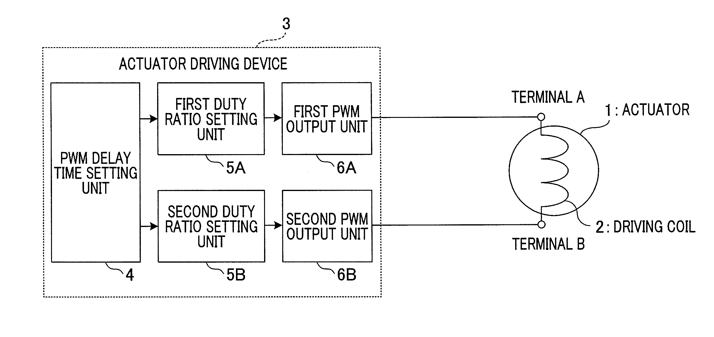
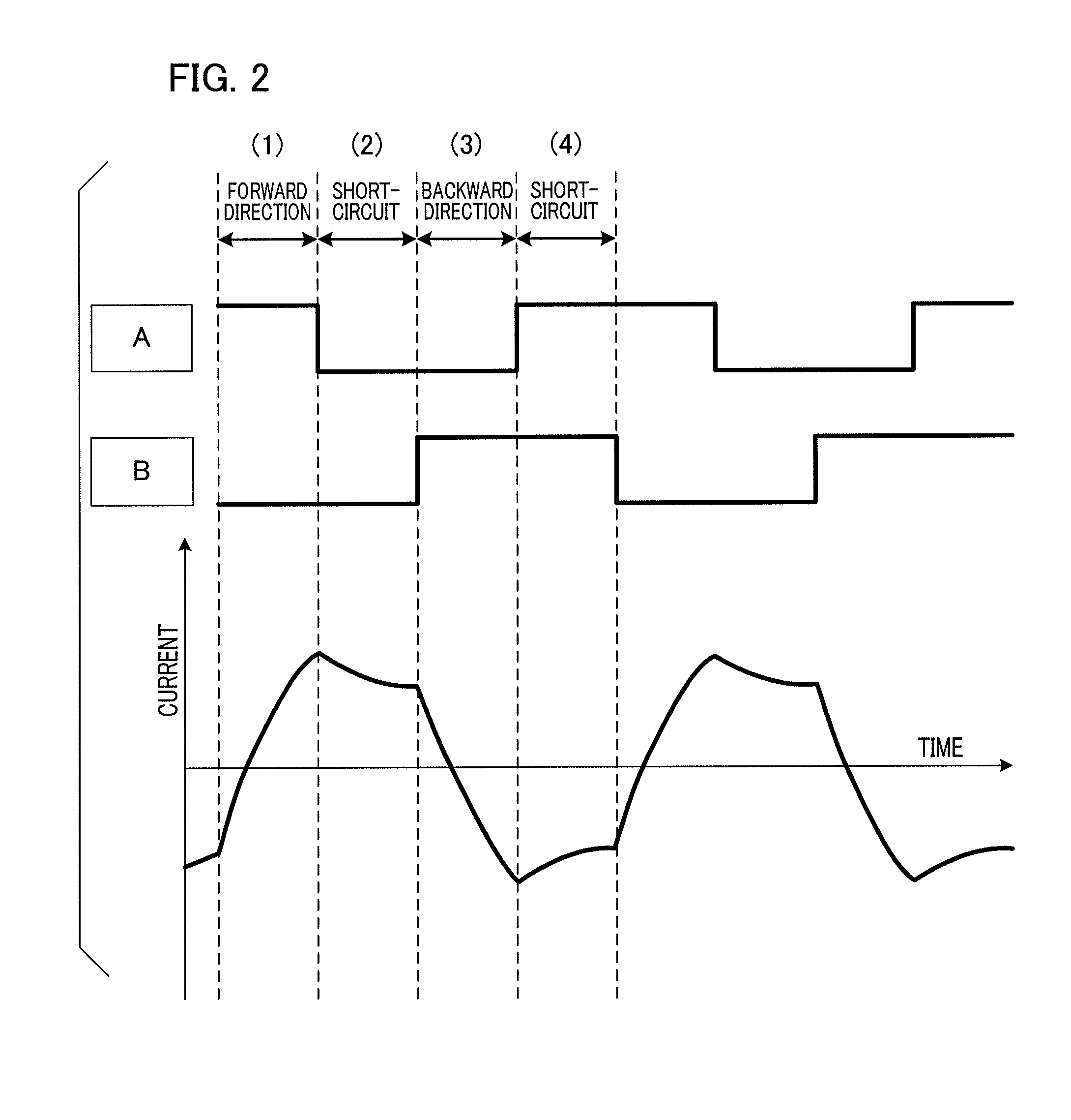
[0017]Hereinafter, a description will be given by taking an example in which the driving control of an actuator is executed by the positive and negative energization method under pulse width modulation control according to an embodiment of the present invention. Note that the actuator driving device according to the present embodiment is applicable to an imaging apparatus including optical elements and an optical member constituting a lens barrel. In this case, the optical elements are a hand shake correction lens, a focus lens, a zoom lens, and the like, and the optical member is a movable member such as a cam tube. Upon application of the present invention to an imaging apparatus, the driving mechanism unit may be configured in any suitable manner, and thus, a description thereof will be omitted.

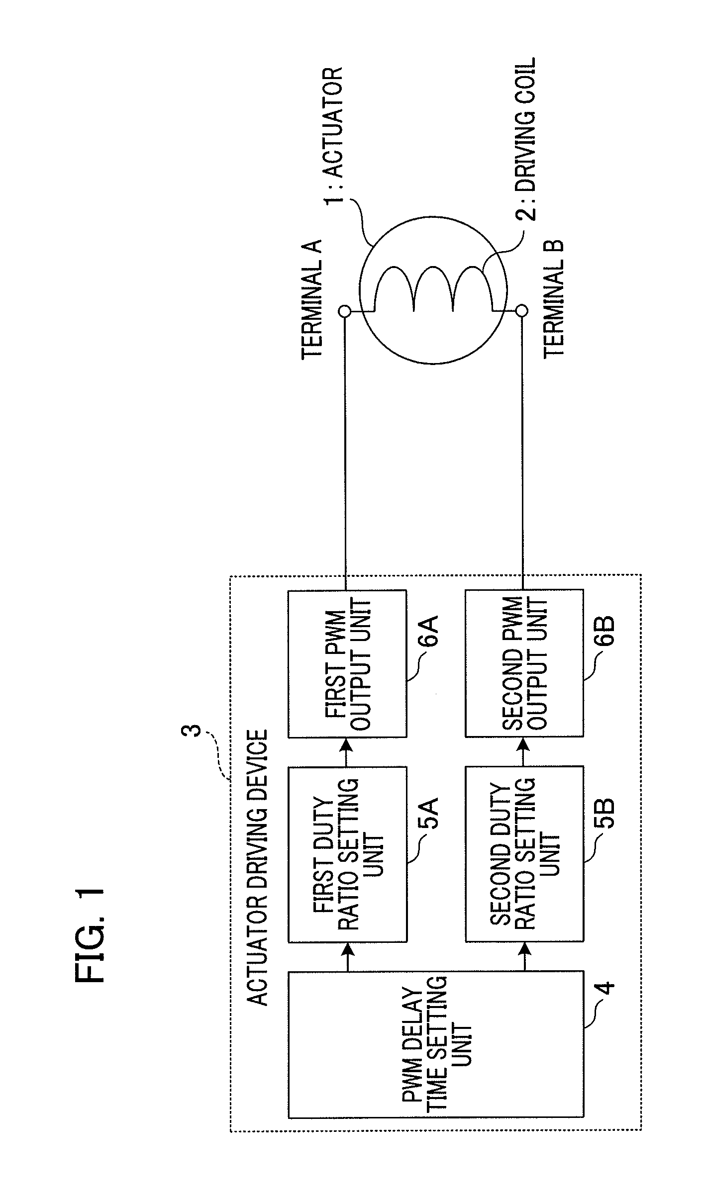
[0018]FIG. 1 is a block diagram illustrating an exemplary configuration of an actuator driving device according to an embodiment of the present invention. An actuator 1 has a driving coil ...


PUM


Abstract

An actuator driving device drives an actuator connected to an output terminal. The control unit of the actuator driving device includes a PWM delay time setting unit, a first duty ratio setting unit, and a second duty ratio setting unit. The PWM delay time setting unit sets a delay time of pulse width modulation control for a driving voltage to be applied to the output terminal and outputs setting information to the first and second duty ratio setting units. The first duty ratio setting unit sets the first duty ratio for a first PWM output unit, and the second duty ratio setting unit sets the second duty ratio for a second PWM output unit. When positive and negative energization is performed, the control unit controls to reduce the amount of change in current in the current peak of a PWM waveform by providing a short-circuit period in response to the energization amount.

Description

BACKGROUND OF THE INVENTION[0001]1. Field of the Invention[0002]The present invention relates to an actuator driving device to be applied to an imaging apparatus or the like and a method for controlling the same.[0003]2. Description of the Related Art[0004]Conventionally, a positive and negative energization method under PWM (Pulse Width Modulation) control due to duty ratio-current characteristics with high linearity has been used as an actuator driving device. However, CMOS (complementary metal-oxide semiconductor) sensors have often been used as imaging elements in recent years, which may lead to the occurrence of phenomenon in which magnetic field noise caused by a change in current under PWM control adversely affects on electric charge information of an imaging element. The cause of the readily occurrence of noise when the positive and negative energization method under PWM control is employed lies in the repetition of energization in the forward direction and energization in t...

Claims


Application Information

Patent Timeline
Patent Type & Authority Applications(United States)
IPC IPC(8): H04N5/225G03B13/34H04N5/232H02P29/00G02B7/08
CPCH04N5/2254G03B13/34H04N5/23296H04N5/23287H02P6/10H02P25/034H02P29/50G03B2205/0069
Inventor KOBUNA, HIROYO
Owner CANON KK
Why Eureka
Try Eureka