LED light and filament thereof

a technology of led filament and led light, which is applied in the direction of lighting and heating apparatus, lighting support devices, lighting source combinations, etc., can solve the problems of short life, heavy power consumption, drawbacks of filament types, etc., and achieve the effect of improving the light color rendering, improving the light emitting angle and efficiency of led filaments, and simple process

Inactive Publication Date: 2014-12-18
SHENZHEN RUNLITE TECH
View PDF6 Cites 135 Cited by
  • Summary
  • Abstract
  • Description
  • Claims
  • Application Information

AI Technical Summary

Benefits of technology

[0016]The present invention has advantages. For example, light color rendering is effectively improved for LED filament due to construction of elongated bar-shaped substrate forming the main body of the LED filament and due to placement of the light emitting composed of blue and red light chips on at least one side of the substrate. In addition, as the substrate is configured to be transparent, light emitting angle and efficiency of the LED filament is also significantly improved. Moreover, the package adhesive layer is formed by molding process leading to simple process, high productivity and yield. Furthermore, production cost is low.

Problems solved by technology

This kind of filament suffers from drawbacks such as short lifetime and heavy power consumption.
Furthermore, it can only generate yellow light and is thus poor in color rendering.
Led light has poor color rendering in entirety.
In addition, a prior art bracket is formed of conductive metal such as copper and alumina into which PPA material is plastic molded and accordingly, it is not light transmissible.
Even optically processed by the lens for a second time, the light transmission angle is still not greater than 165 degree. Moreover, PPA material is subject to yellowing and changes in color, thereby having influence on overall quality of the LED light.
Further, a conventional LED light emitting module is mostly packaged by flat adhesive dispensing technique with low efficiency and yield.
In addition, it causes high cost.

Method used


Image

  • LED light and filament thereof
  • LED light and filament thereof
  • LED light and filament thereof

Examples


Embodiment Construction

[0026]It is noted that, in case no interference is resulted in, the embodiments and features contained therein may be combined with each other. The present invention is described in greater detail in conjunction with the accompanying drawings and embodiments.

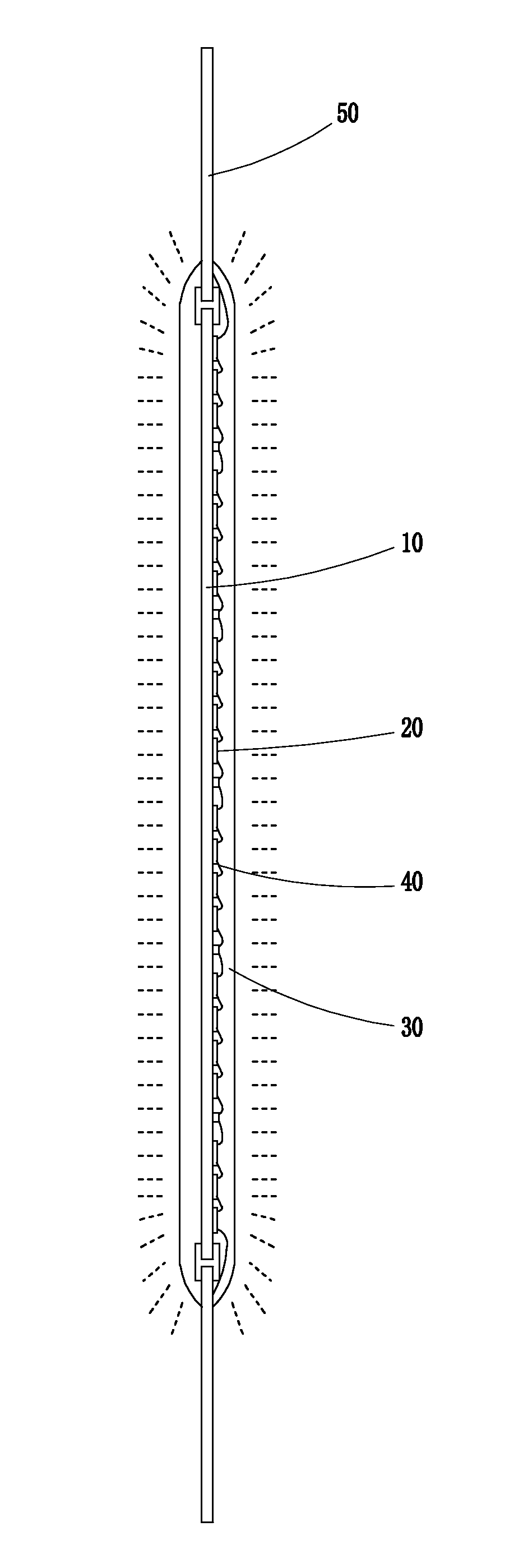
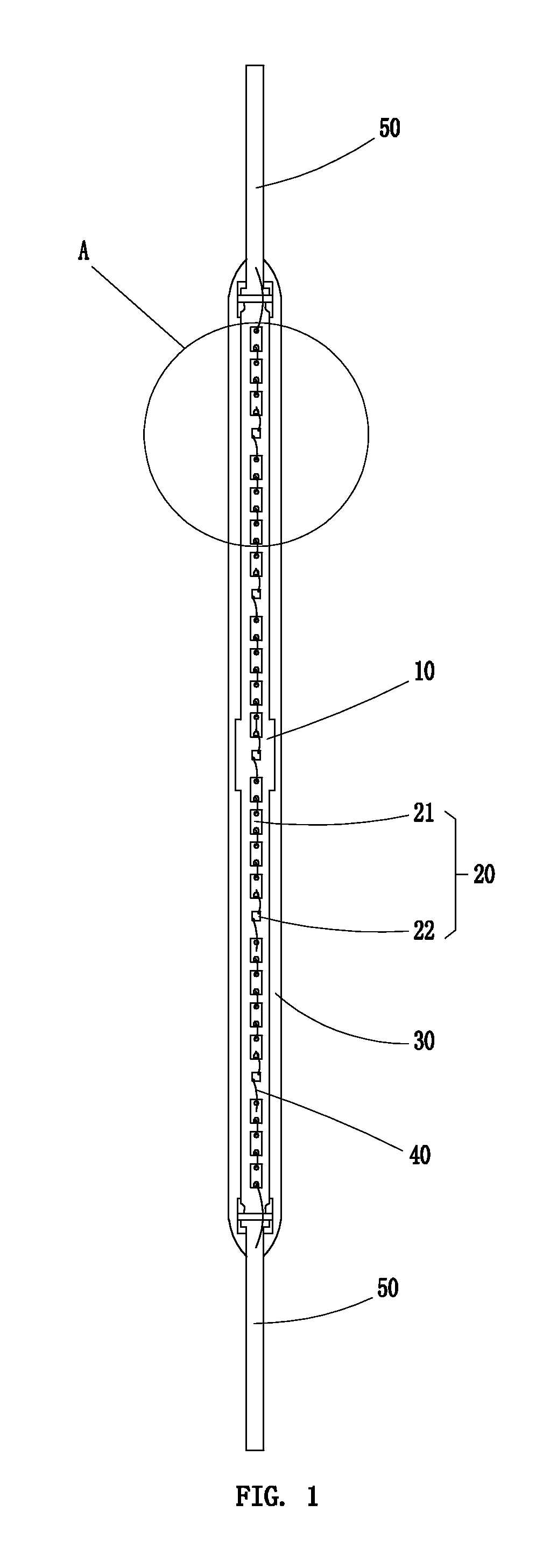
[0027]As shown in FIG. 1-9, the invention provides a LED filament including a substrate 10, a light emitting unit 20 and a package adhesive layer 30.

[0028]The substrate 10 is set to be of an elongated bar-shaped construction to constitute a main body of the LED filament. In present embodiment, the length of the substrate ranges from 5.00 mm to 200.00 mm, the width thereof ranges from 0.50 to 10.00 mm, and height thereof ranges from 0.10 mm to 5.00 mm.

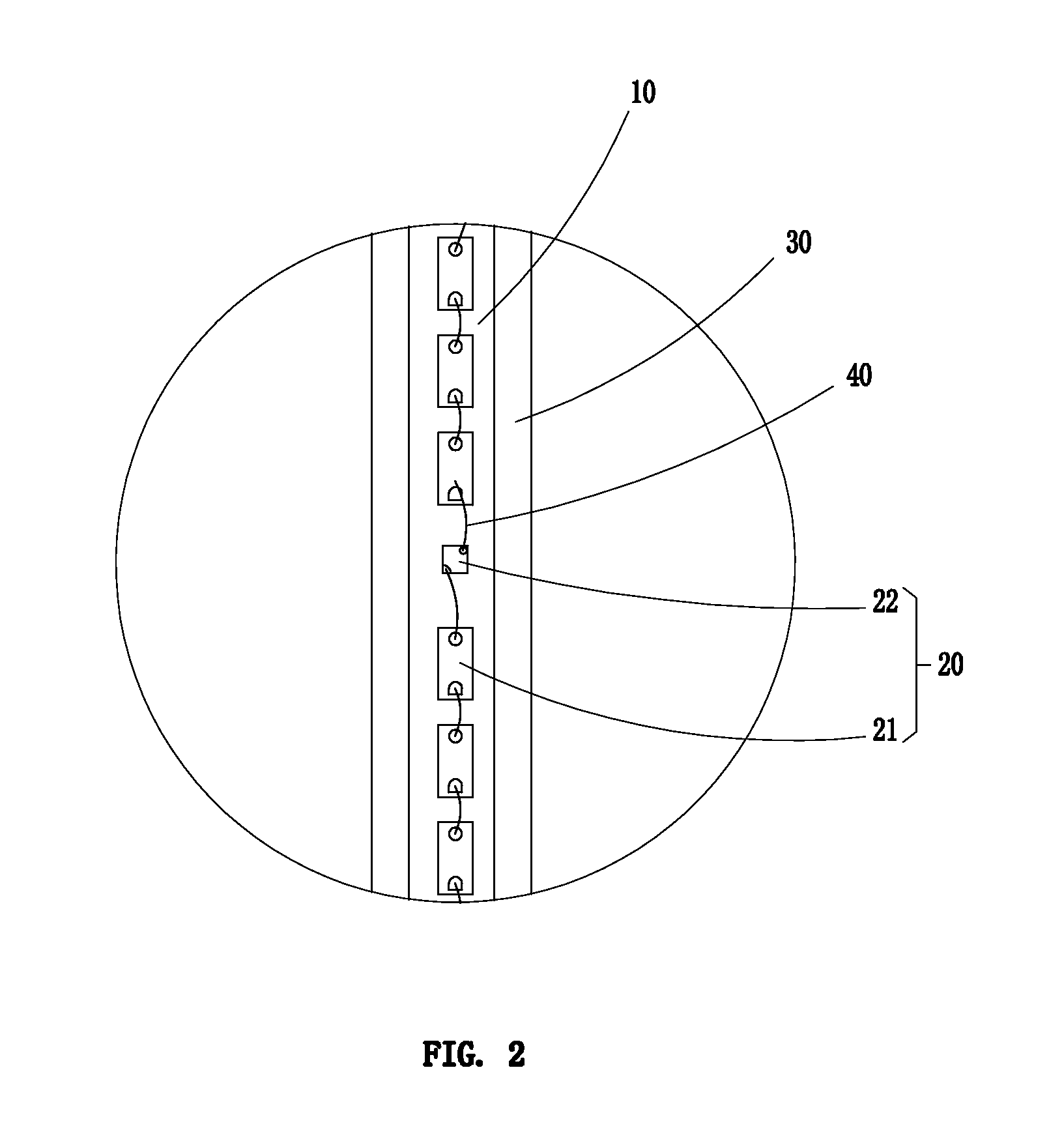
[0029]With reference to FIGS. 2, 4 and 7, the light emitting unit 20 is fastened onto at least one side surface of the substrate 10, and includes plural regularly distributed blue light chips 21 and red light chips 22. The blue light chips 21 and red light chips 22 are sequentially ...


PUM


Abstract

The invention discloses a LED lamp and filament thereof. The LED filament includes a substrate, a light emitting unit secured onto at least one side surface of the substrate, and a package adhesive layer surrounded on the periphery of the light emitting unit; the substrate is configured to be of an elongated bar construction; the light emitting unit comprises a plurality of blue light chips and red light chips regularly distributed on the substrate and sequentially connected to one another in series. For the LED filament of the invention, as the light emitting unit composed of blue and red light chips is disposed on the substrate, the LED filament has high color rendering and large light radiation angle.

Description

FIELD OF THE INVENTION[0001]The present invention relates to LED lighting technology and more particularly, relates to a LED light and filament thereof.BACKGROUND OF THE INVENTION[0002]A filament of a traditional lighting lamp is directly constructed of illuminant metal filament such as tungsten filament. This kind of filament suffers from drawbacks such as short lifetime and heavy power consumption. Furthermore, it can only generate yellow light and is thus poor in color rendering.[0003]With the development of science and technology, LED light has gradually replaced of traditional lighting lamps. A conventional LED light is provided with a light emitting module, and includes a bracket of square or circle type, a LED chip disposed at one side of the bracket, and a lens covered on a surface of the LED chip. For a conventional LED light, fluorescent powder is generally provided on a blue light LED chip for creating white light. Led light has poor color rendering in entirety. In additi...

Claims


Application Information

Patent Timeline
Patent Type & Authority Applications(United States)
IPC IPC(8): F21K99/00F21V23/06
CPCF21K9/50F21K9/17F21K9/23F21Y2103/10F21Y2107/90F21Y2113/13F21Y2115/10H01L25/0753H01L25/0756H01L2924/0002H01L2924/00
Inventor FENG, YUNLONG
Owner SHENZHEN RUNLITE TECH
Why Eureka
Try Eureka