Heat integrated reformer with catalytic combustion for hydrogen production

a hydrogen production and catalyst technology, applied in the direction of energy input, chemical/physical/physicochemical processes, bulk chemical production, etc., can solve the problems of increasing resource consumption and cost, inefficient transportation, and inability to easily downscale the technology of large-scale hydrogen production, so as to facilitate the introduction and distribution of fuel, facilitate the collection and exit of combustion products, and promote the effect of reformation reactions

Active Publication Date: 2014-12-18
HELBIO
View PDF3 Cites 15 Cited by
  • Summary
  • Abstract
  • Description
  • Claims
  • Application Information

AI Technical Summary

Benefits of technology

[0019]In another aspect of the invention the integrated combustor / steam reformer assembly includes a multitude of tubular sections defined by cylindrical walls separated from each other and supported on each end on plates machined as to allow the cylindrical walls to pass through them and to be in fluid connection with only one side of the plate. The sub-assembly of the tubular sections and the plates is enclosed with a cylindrical housing which isolates the space defined by the inner part of the housing and the plates from being in fluid connection with the surroundings. The inside wall of the tubular sections is in contact with fecralloy sheets, preferably corrugated, coated with a catalyst that induces the desired reaction in the combustor feed. The outside space of the tubular sections contains a catalyst in pellet form that induces the desired reaction in the reformer feed or it contains fecralloy sheets, preferably corrugated, coated with a suitable catalyst that promotes reformation reactions. The assembly also includes an appropriately shaped reactor head that facilitates the introduction and distribution of the fuel and air mixture inside the tubular sections and an appropriately shaped reactor head that facilitates the collection and exit of the combustion products. A flow passage on one side of the cylindrical housing introduces the fuel and steam mixture in the enclosed reforming section. A second flow passage on the opposite side of the cylindrical housing facilitates the withdrawal of the reforming products.

Problems solved by technology

The reason is that the technology for large scale hydrogen production can not be easily downscaled.
The problem lies in the low energy density of hydrogen which makes its transportation very inefficient and expensive.
Transporting hydrogen in compressed or liquid form requires specialized and bulky equipment that minimizes the amount that can be safely carried, increasing resource consumption and cost.
This is a rather inefficient arrangement since the hydrogen producing reforming reaction forms a small part of overall reactor.
Materials limitations also dictate the avoidance of extremely high temperatures (>1000° C.) for the reforming reactor tubes, further limiting the ability to place the combustion burners in close proximity to the reforming tubes.
All these mean that traditional steam methane reforming reactor configurations are very large and new configurations must be developed to decrease the size and the cost of such systems.
Such a configuration presents significant difficulties, such as excessive pressure drop, which will limit its effectiveness for large scale systems.
Although this system resulted in a compact configuration the replacement of the catalyst is problematic and as a result the whole reactor must be replaced when the catalyst effectiveness for either the combustion or the reforming reaction declines.
Since the heat source is a burner the limitation of burner placement in relation to the reforming catalyst placement prevent the construction of a compact low cost system.
However, in such a configuration catalyst replacement is problematic.
Such a configuration results in high rates of heat transport from the combustion side to the reforming side.
However, in such a configuration catalyst replacement is a problem

Method used


Image

  • Heat integrated reformer with catalytic combustion for hydrogen production
  • Heat integrated reformer with catalytic combustion for hydrogen production
  • Heat integrated reformer with catalytic combustion for hydrogen production

Examples


Embodiment Construction

[0028]The present invention is described in detail with reference to a few preferred embodiments illustrated in the accompanying drawings. The description presents numerous specific details included to provide a thorough understanding of the present invention. It will be apparent, however, to one skilled in the art that the present invention can be practiced without some or all of these specific details. On the other hand, well known process steps, procedures and structures are not described in detail as to not unnecessarily obscure the present invention.

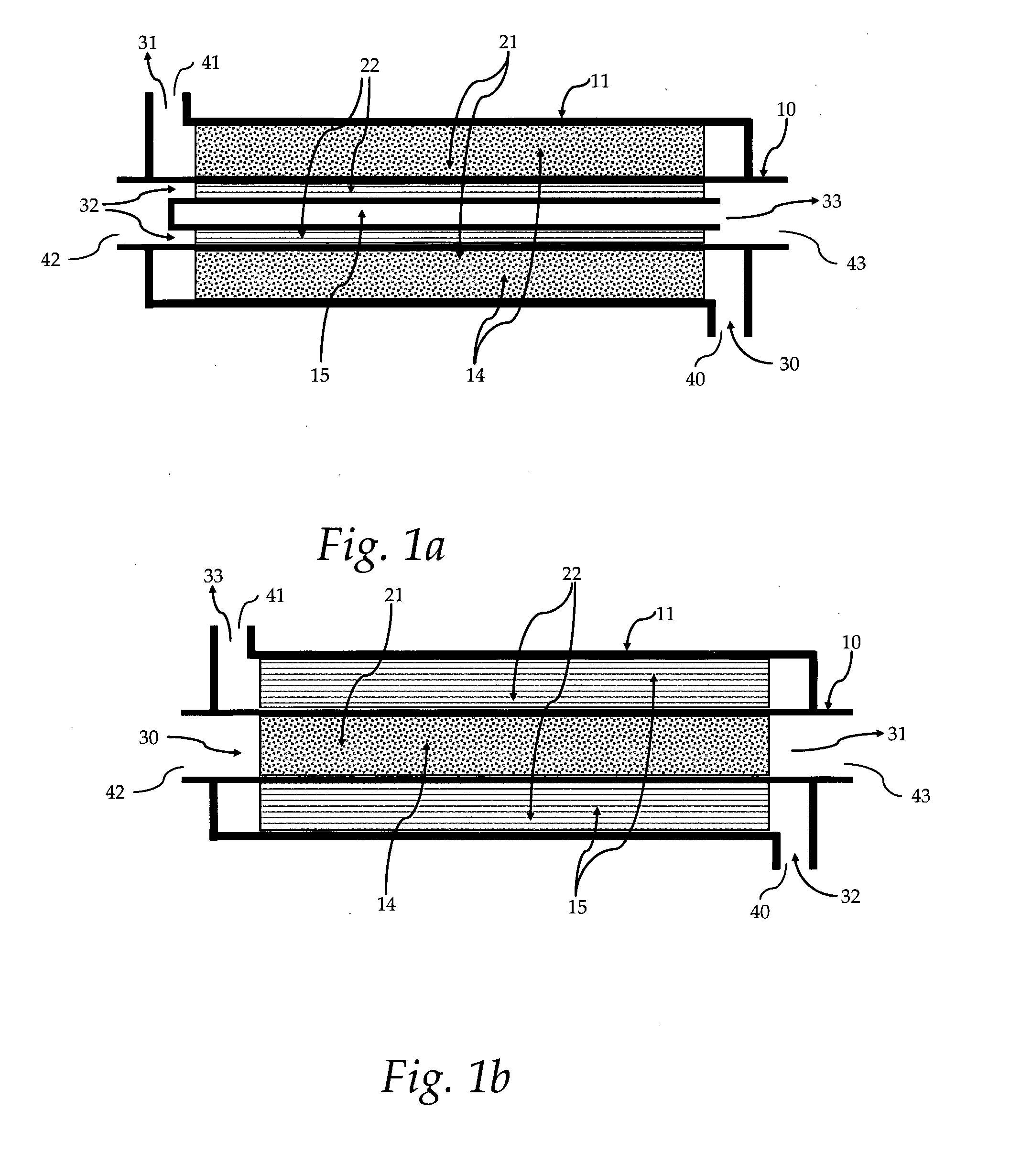
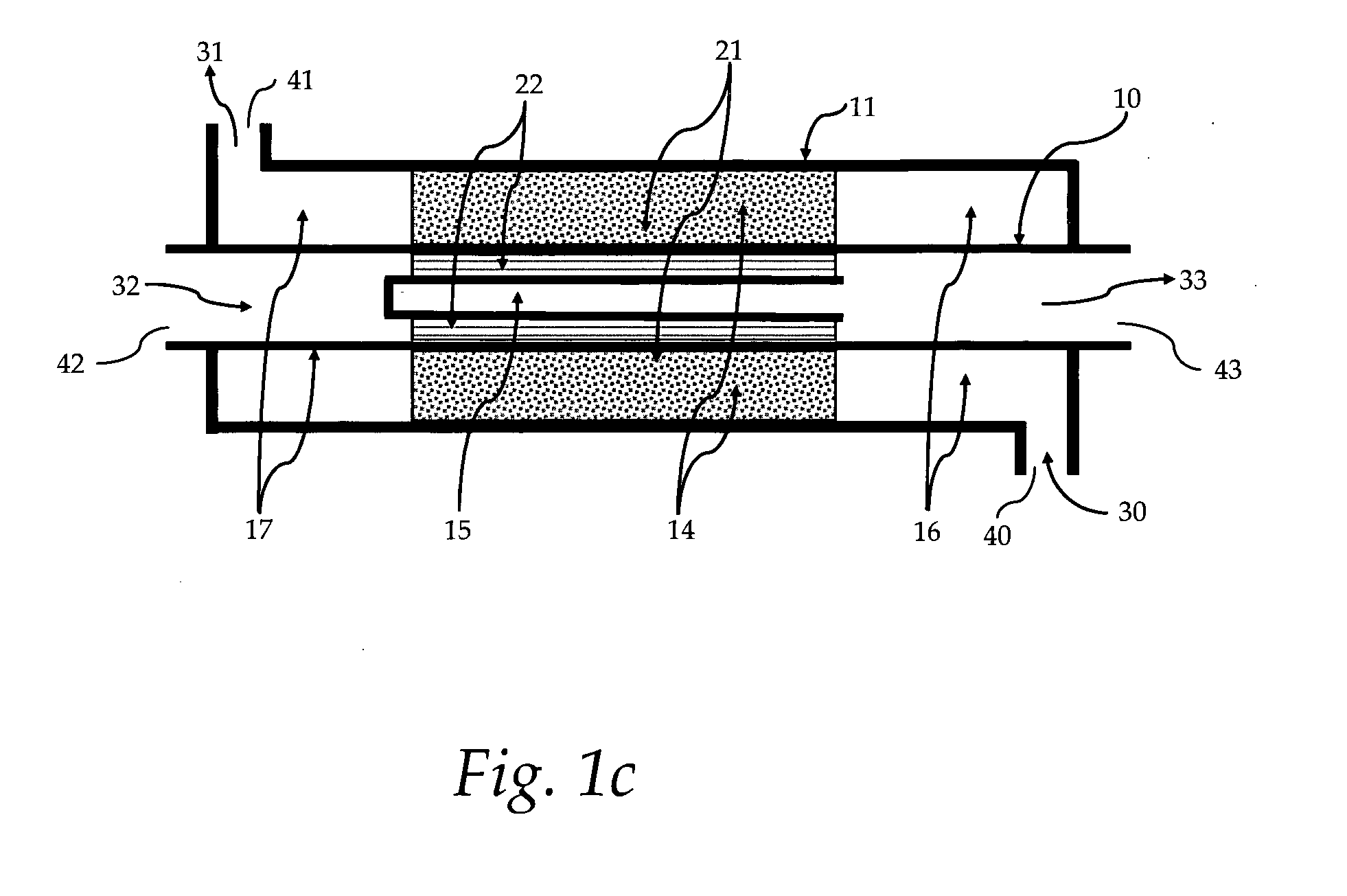
[0029]FIG. 1A illustrates the heat integrated reformer according to one embodiment of the present invention. The integrated combustor / steam reformer assembly includes a tubular section defined by a cylindrical wall 10 that separates the combustion zone 15 from the reforming zone 14. The assembly housing 11 acts as the reactor wall and defines an axially extending concentric annular passage in heat transfer relation with the tubular ...


PUM

PropertyMeasurementUnit
surface areaaaaaaaaaaa
heataaaaaaaaaa
energy densityaaaaaaaaaa

Abstract

A heat integrated steam reformer, which incorporates a catalytic combustor, which can be used in a fuel processor for hydrogen production from a fuel source, is described. The reformer assembly comprises a reforming section and a combustion section, separated by a wall. Catalyst (21) able to induce the reforming reactions is placed in the reforming section, either in the form of pellets or in the form of coating on a suitable structured catalyst substrate such as fecralloy sheets. Catalyst (22) able to induce the combustion reactions is placed in the combustion section in the form of coating on suitable structured catalyst substrate such as fecralloy sheet. A steam and fuel mixture (30) is supplied to the reforming section (14) where it is reformed to produce hydrogen. A fuel and an oxygen (32) containing gas mixture is supplied to the combustion section where it is catalytically combusted to supply the heat for the reformer. The close placement of the combustion and reforming catalysts facilitate efficient heat transfer. Multiple such assemblies can be bundled to form reactors of any size. The reactor made of this closely packed combustion and reforming sections is very compact.

Description

FIELD OF THE INVENTION[0001]This invention relates to reforming reactor assemblies for hydrogen production and more particular to reactors where hydrocarbons or oxygenates are reformed to produce a hydrogen rich stream.BACKGROUND OF THE INVENTION[0002]Hydrogen is used in many chemical processes as for example in ammonia synthesis and in oil refining, in very large quantities. There are other processes which require hydrogen in smaller quantities, as for example oil hydrogenation plants, glassblowing operations, cooling applications in electricity production, photovoltaic materials processing, etc. Furthermore, the use of hydrogen as an alternative energy vector has gained wide acceptance and is progressing along the road to implementation. Hydrogen can be used in both internal combustion engines and fuel cells. Particularly, its usage in fuel cells to produce electricity or to co-generate heat and electricity represents the most environmentally friendly energy production process due...

Claims


Application Information

Patent Timeline
Patent Type & Authority Applications(United States)
IPC IPC(8): C01B3/38
CPCC01B3/386B01J8/0214C01B3/323C01B3/384C01B2203/0811C01B2203/1017C01B2203/1058B01J19/2485B01J8/025B01J8/0285B01J8/0292B01J2208/00132B01J2208/00309B01J2208/00495B01J2208/00557B01J2208/0084B01J2219/00265Y02P20/52Y02P20/133
Inventor VERYKIOS, XENOPHONHALKIDES, THOMASSTAVRAKAS, ANDREASBASAGIANNIS, ARIS
Owner HELBIO
Why Eureka
Try Eureka