Real-time display of vasculature views for optimal device navigation

Active Publication Date: 2014-12-18
KONINKLJIJKE PHILIPS NV
View PDF3 Cites 21 Cited by
  • Summary
  • Abstract
  • Description
  • Claims
  • Application Information

AI Technical Summary

Benefits of technology

[0028]According to another embodiment, rather than constraining retrieval/optimization to the angular margin around the projection direction of the current image, the smoothness of transition is achieved by briefly fading in and then out one image at a time from a sequence of sub-optimal projection images before the projection image with the best or better score is eventually being displayed. The sub-optimal images as determined during optimization have scores less than the best or better image and the sequence in which the images are faded in is determined according to their sc

Problems solved by technology

However, the 3D vasculature geometry is co

Method used


Image

  • Real-time display of vasculature views for optimal device navigation
  • Real-time display of vasculature views for optimal device navigation
  • Real-time display of vasculature views for optimal device navigation

Examples


Example

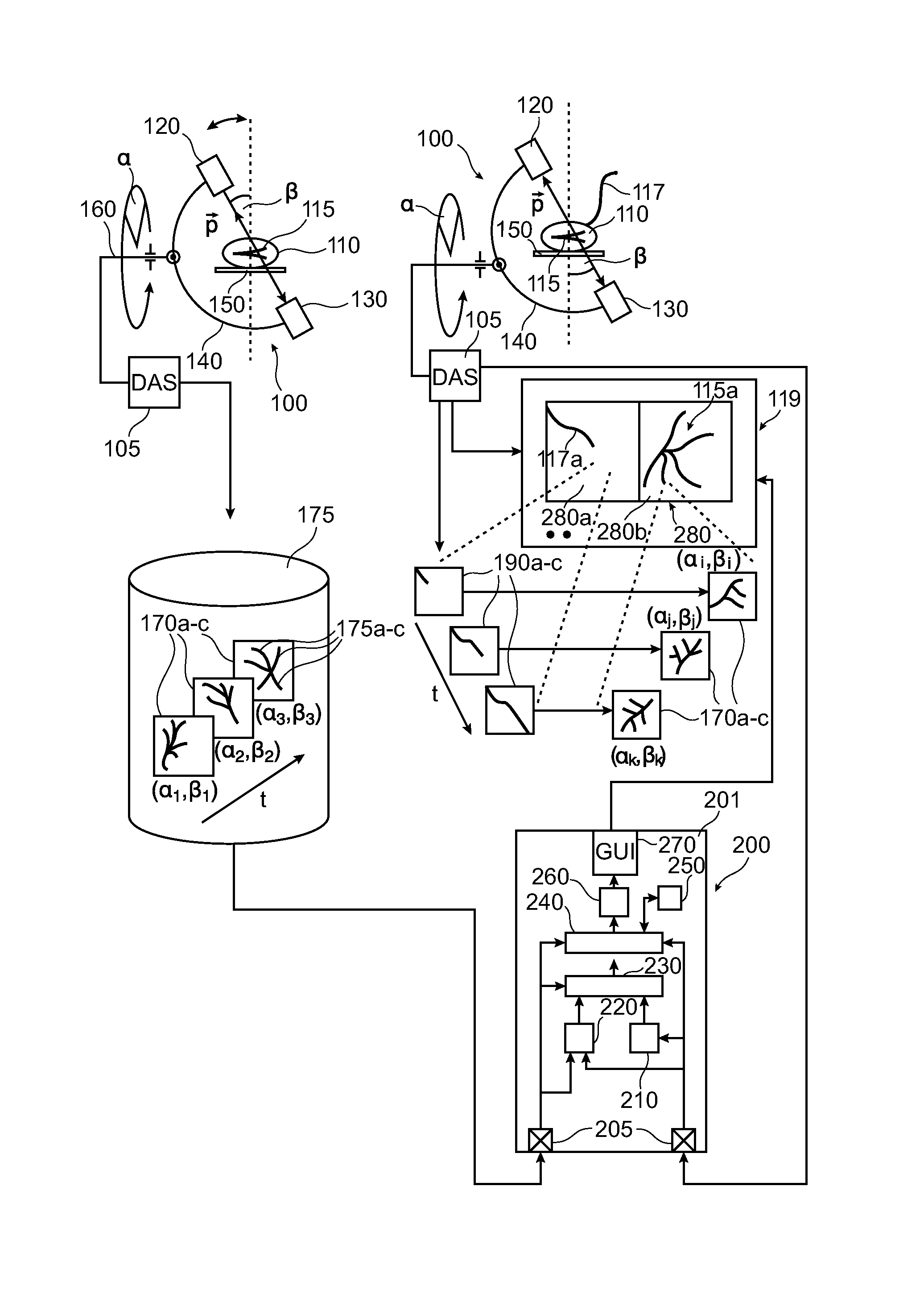
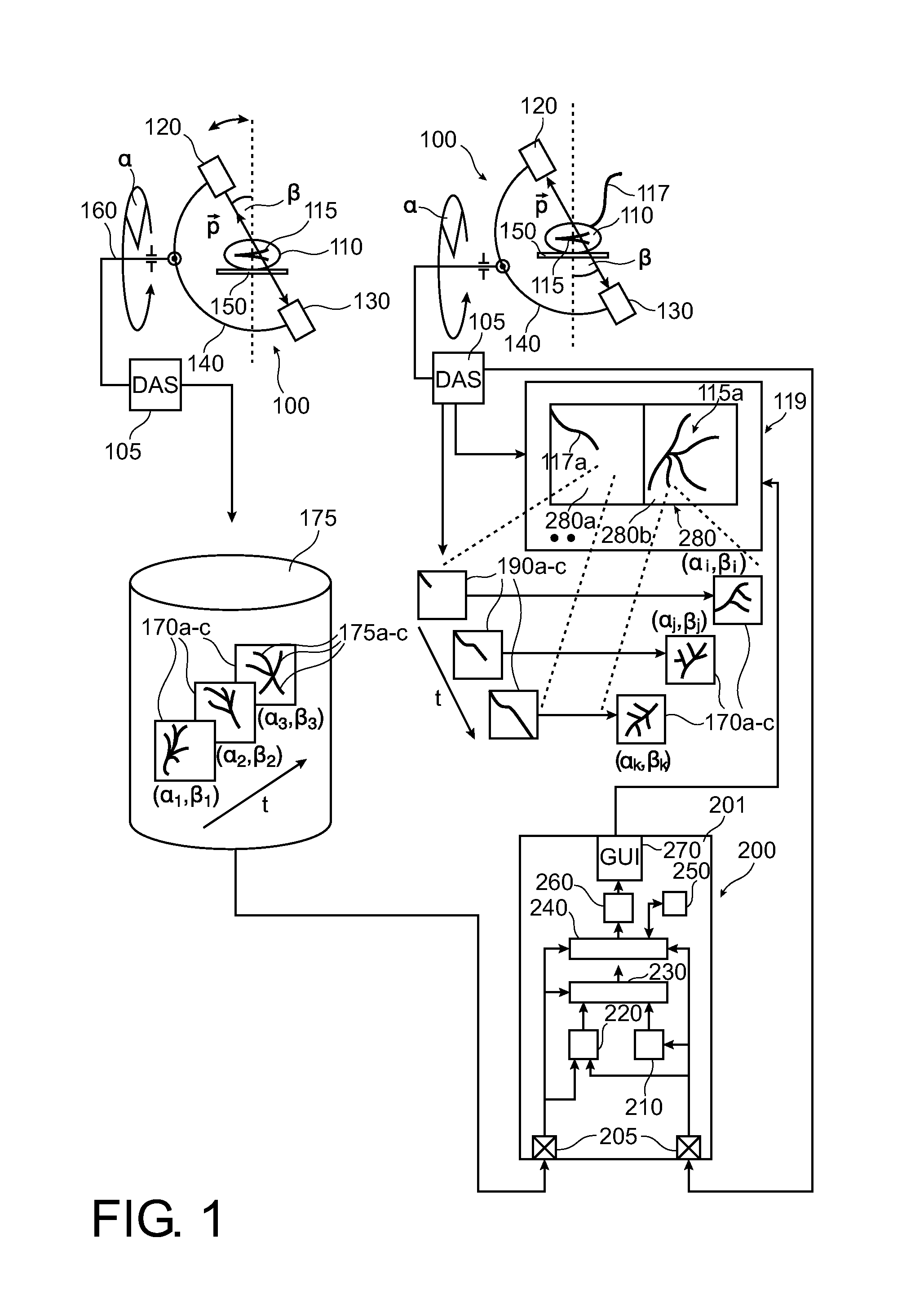
[0041]To the left of FIG. 1 there is shown an x-ray imager 100 of the C-arm type. X-ray imager 100 is used in a preparatory planning phase to acquire a sequence of x-ray projection images 170a-c of an organ of interest to support in a later phase an intervention.

[0042]In one embodiment, the organ of interest is a patient 110's heart, in particular its coronary vasculature 115.

[0043]In the planning phase the patient is placed on an examination table 115. Imager 100 comprises a rigid C-arm structure 140 journaled on a bearing 160. Journaling allows rotation of C-arm 140 around a first axis passing through journaling 160. C-arm structure 140 can thus be positioned at various rotation angles • around vasculature 115. C-arm 140 is further rotatable around an axis perpendicular to the first axis to so assume different angulation angles • so that c-arm 140 enjoys at least 2 degrees of freedom.

[0044]C-arm140 carries at one of its ends an x-ray source 130 and at the other end a detector 120 ...


PUM


Abstract

An apparatus configured to generate for display a plurality of vasculature (115) views (170a-c) alongside a live fluoroscopy image (190a). The views are selected in such a way that they allow visualizing the 3D structure of the vasculature segment in which the device (117) is currently navigating. The view is best relative to one or a weighted average of a plurality of goodness of view standards. As the device progresses and new fluoroscopy images (190b-c) are acquired, the views (170i-k) are updated accordingly.

Description

FIELD OF THE INVENTION[0001]The present invention relates to an apparatus for aiding in navigating a device in a network of tubular structures, to a method for aiding in navigating a device in a network of tubular structures, to a medical x-ray imaging support system, to a computer program element, and to a computer readable medium.BACKGROUND OF THE INVENTION[0002]During a PCI (Percutaneous Coronary Intervention) a guide-wire is introduced in and advanced along cardiac vessels to support treatment of cardiac stenosis.[0003]When navigating in the vessels, the clinician relies on a static image of the vasculature shown next to a live fluoroscopic image.[0004]The vasculature image typically depicts the vessels from the same perspective as the fluoroscopic image. However, the 3D vasculature geometry is complex, and at times difficult to represent.[0005]WO 2011 / 086475 describes a system for navigating an interventional device.SUMMARY OF THE INVENTION[0006]There may therefore be a need fo...

Claims


Application Information

Patent Timeline
IPC IPC(8): A61B6/12A61B19/00A61B6/00
CPCA61B6/12A61B6/5229A61B6/463A61B2019/5265A61B6/504A61B19/5244A61B2019/5238A61B6/485A61B6/4441A61B6/481A61B6/487A61B6/503A61B34/20A61B90/37A61B2034/2065A61B2090/367A61B2090/376
Inventor AUVRAY, VINCENT MAURICE ANDREFLORENT, RAOUL
Owner KONINKLJIJKE PHILIPS NV
Why Eureka
Try Eureka