
System and method of identifying sources associated with biological rhythm disorders

a biological rhythm and source technology, applied in the field of biological rhythm disorders, can solve the problems of difficult treatment of heart rhythm disorders, affecting the normal functioning of the heart rhythm, and affecting the normal functioning of the heart rhythm

Active Publication Date: 2014-12-18
RGT UNIV OF CALIFORNIA +2
View PDF1 Cites 43 Cited by
  • Summary
  • Abstract
  • Description
  • Claims
  • Application Information

AI Technical Summary

Benefits of technology

The present invention is a method and system for identifying the source(s) of heart rhythm disorders and treating them. It can detect and identify complex rhythms that exhibit complex activation patterns and can be influenced by complex signals. This invention is applicable to identifying the source(s) of various biological rhythm disorders, such as seizures, bladder instability, and irritable bowel syndrome. It can also detect and alter the rotation of the source(s) of the disorder, regardless of the underlying cause. The invention can help to quickly determine the source(s) of the disorder and can thus facilitate treatment.

Problems solved by technology

Heart rhythm disorders are common and represent significant causes of morbidity and death throughout the world.
While under normal conditions the sinus node keeps the heart in sinus rhythm, under certain conditions rapid activation of the normal sinus node can cause inappropriate sinus tachycardia or sinus node reentry, both of which also represent heart rhythm disorders.
Treatment of heart rhythm disorders—particularly complex rhythm disorders of AF, VF and VT—can be very difficult.
Pharmacologic therapy for complex rhythm disorder is not optimal.
However, in complex rhythm disorders ablation is often difficult and ineffectual because tools that identify and locate a cause (source) of the heart rhythm disorder are poor and hinder attempts to deliver energy to a correct region of the heart to eliminate the disorder.
However, even in simple heart rhythm disorders, ablating the cause of a heart rhythm disorder is challenging and experienced practitioners often require hours to ablate simple rhythm disorders that show consistent beat-to-beat activation patterns, such as atrial tachycardia.
There are few, if any, known systems and methods that have been successful with respect to identifying the sources or causes for the direct treatment of complex rhythm disorders such as AF, VF or polymorphic VT.
For instance, when a signal for a sensor location in AF includes 5, 7, 11 or more deflections, it is difficult if not impossible to identify which deflections in the signal are local to the sensor location in the heart (i.e., local activation onset) versus a nearby sensor location in the heart (i.e., far-field activation onset) or simply noise from another part of the patient's heart, other anatomic structures or external electronic systems.
The foregoing deflections make it difficult if not impossible to identify activation onset times of the beats in a signal at a sensor location.
However, while these approaches have been validated in animal models, they may not be successful in finding and treating sources of atrial fibrillation in humans.
As a result, CFAE are often unstable (e.g., varying in location over time or disappearing altogether), are found in large and widespread areas of heart tissue rather than being just in small discrete areas, and are usually identified inconsistently by a variety of relatively subjective criteria.
Therefore, CFAE sites, in larger multicenter trials, have turned out to be poor targets for AF treatment with long term success (Oral, Circulation 2007; Oral J Am Coll Cardiol, 2009).
Using traditional analyses, electrogram shapes are often difficult to interpret in complex rhythm disorders.
Sources precess (move) in limited spatial areas, such that traditional analyses from a fixed set of electrodes may not comprehend rotational activation (associated with a rotor) or centrifugal activation (associated with a focal source) when the source moves relative to the electrodes during and between consecutive beats.
Electrical noise due to a variety of reasons, such as movement artifact from the movement of recording sensors or their physiological interface (e.g. body surface, cardiac tissue, etc.), poor electrode contact with the physiological interface, underlying electrical noise from the ambient environment, or near-field and far field signals, can make determination of activation particularly difficult in a rhythm with already underlying complexity.
First, disorganized activation can arise if activation from the source undergoes disorganization away from its center or core (e.g., FIG. 16, left display).
In this case, disorganized activation can surround the source but not perturb it, in which case, the central functionality of the source is largely unperturbed.
This disorganization can also be due to abnormalities in nervous system function or innervation, such as the autonomic nervous system, resulting in abnormal spatially varying electrical properties in the tissue of the organ (e.g., heart).
This may alter the rate or regularity of the source, causing the source to appear irregular or complex (e.g., FIG. 18).
This may cause the source to precess (move) in more constrained spatial areas, or potentially to meander in less constrained spatial areas.
Treatment of dominant source(s) may cause paradoxical disorganization of the arrhythmia, because regions are no longer organized by these source(s), yet may also yield long-term treatment success if remaining non-dominant sources are less capable of sustaining the arrhythmia alone.
Finally, treatment of non-dominant sources may cause organization of the arrhythmia using conventional analytical metrics.

Method used


Image

  • System and method of identifying sources associated with biological rhythm disorders
  • System and method of identifying sources associated with biological rhythm disorders
  • System and method of identifying sources associated with biological rhythm disorders

Examples


Embodiment Construction

[0085]A system and method for identifying one or more sources of biological rhythm disorder (e.g., heart rhythm disorders) are disclosed herein. In the following description, for the purposes of explanation, numerous specific details are set forth in order to provide a thorough understanding of example embodiments. It will be evident, however, to one skilled in the art, that an example embodiment may be practiced without all of the disclosed specific details.

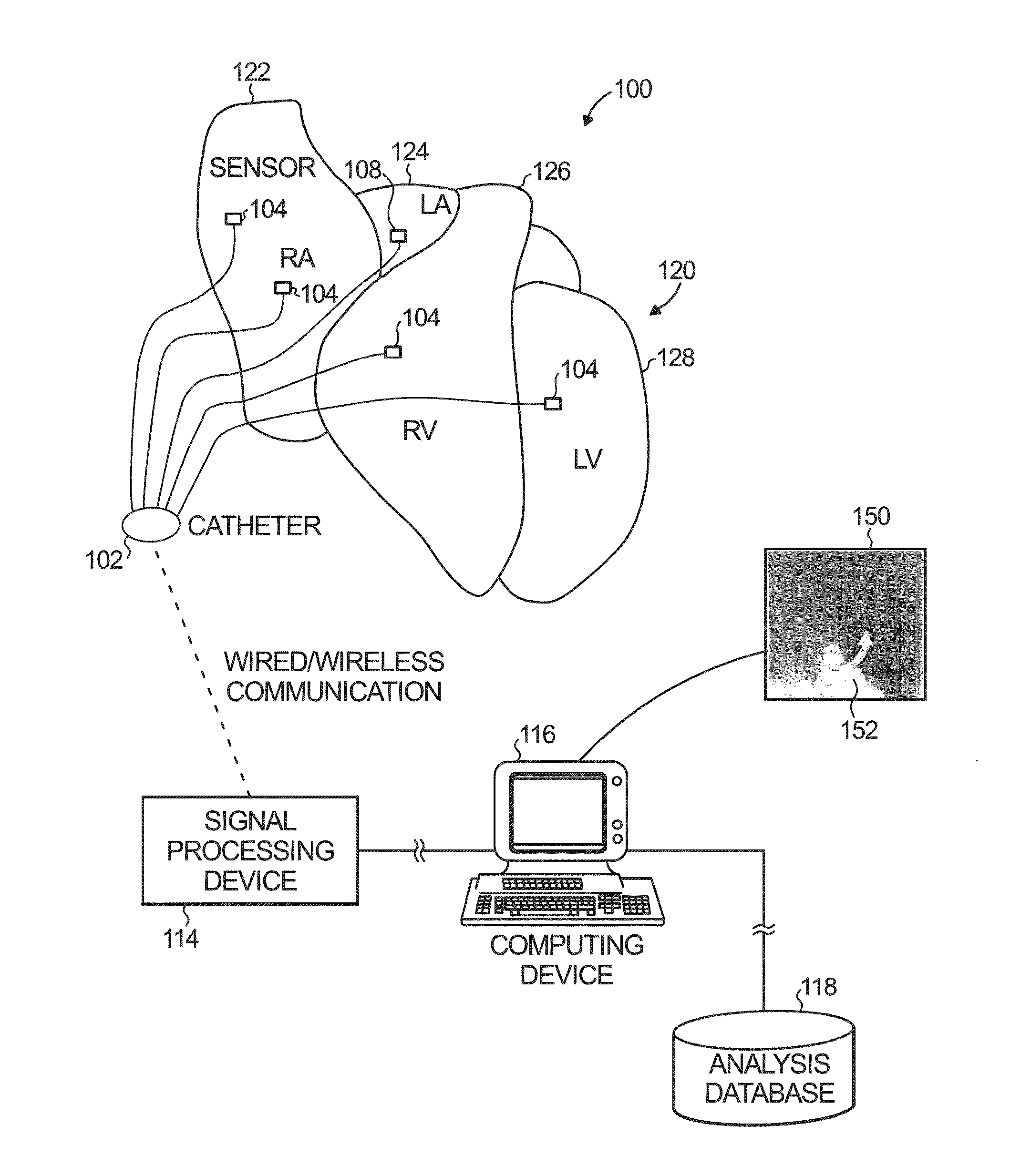
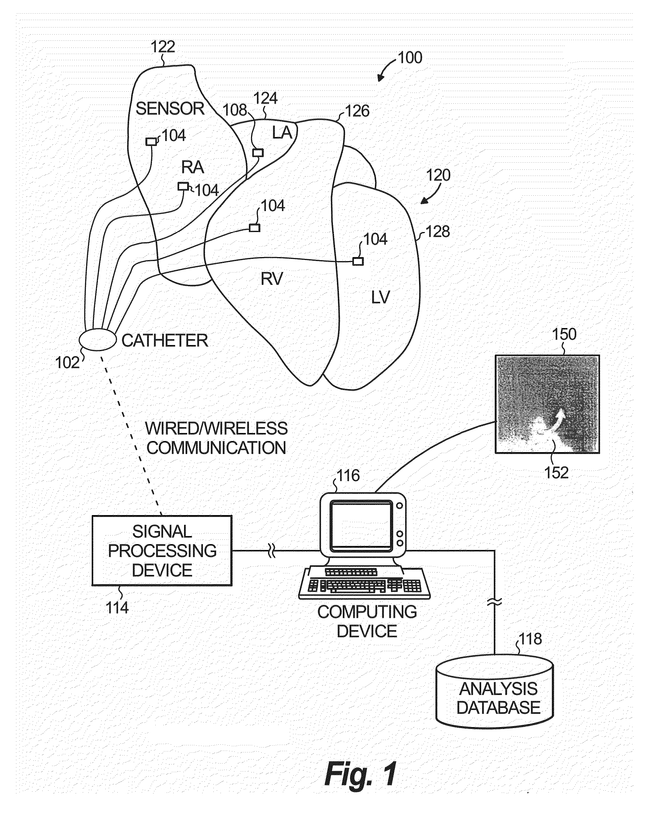
[0086]FIG. 1 illustrates an example system 100 to identify a source (or sources) of a biological rhythm disorder (e.g., heart rhythm disorder) in a human patient. Specifically, the example system 100 is configured to access cardiac information (signals) collected / detected from the patient's heart in connection with the heart rhythm disorder. The system 100 is further configured to process the signals in order to determine at least one spatial area including one or more spatial elements about which there is progressive angular de...


PUM


Abstract

An example system and method associated with identifying and treating a source of a heart rhythm disorder are disclosed. In accordance with therewith, a spatial element associated with a region of the heart is selected. Progressive rotational activations or progressive focal activations are determined in relation to the selected spatial element. A plurality of indexes of progressive rotational activations or progressive focal activations over time is formed. One or more indexes are selected from the plurality of indexes that indicate consistency of the successive rotational activations or the progressive focal activations in relation to a portion of the region of the heart

Description

RELATED APPLICATIONS[0001]This application is a continuation-in-part of U.S. application Ser. No. 13 / 844,562, filed Mar. 15, 2013, and claims the benefit of the priority of U.S. Provisional Application No. 61 / 973,626, filed Apr. 1, 2014, each of which is incorporated herein by reference in its entirety. This application further incorporates herein by reference in their entireties U.S. application Ser. No. 12 / 576,809, filed on Oct. 9, 2009, issued as U.S. Pat. No. 8,521,266; U.S. application Ser. No. 13 / 081,411, filed Apr. 6, 2011, issued as U.S. Pat. No. 8,700,140; U.S. application Ser. No. 13 / 470,705, filed May 14, 2012; and U.S. application Ser. No. 13 / 559,868, filed Jul. 27, 2012.GOVERNMENT RIGHTS[0002]This invention was made with government support under Grants R01 HL83359 and HL103800 from the National Institutes of Health. The government has certain rights in the invention.BACKGROUND[0003]1. Field[0004]The present application relates generally to biological rhythm disorders. M...

Claims


Application Information

Patent Timeline
IPC IPC(8): A61B5/024A61B5/02A61N1/368A61B5/00A61B18/12A61N1/32
CPCA61B5/02405A61B18/12A61N1/327A61B2018/00577A61B5/4839A61B5/02028A61B5/7282A61N1/368A61B5/0006A61B5/287
Inventor NARAYAN, SANJIVBRIGGS, CAREY ROBERTSEHRA, RUCHIR
Owner RGT UNIV OF CALIFORNIA
Learn More