Combustion chamber of a combustor for a gas turbine

a gas turbine and combustion chamber technology, applied in the field of combustion chambers of gas turbines, can solve the problems of insufficient angle of attack on subsequent turbine vanes or blades, pulsation and vibration within the combustion chamber, and many problems in known combustion chambers, etc., to achieve the effect of increasing the strength of the segment, high temperature and creep strength

Active Publication Date: 2014-12-25
SIEMENS ENERGY GLOBAL GMBH & CO KG
View PDF2 Cites 29 Cited by
  • Summary
  • Abstract
  • Description
  • Claims
  • Application Information

AI Technical Summary

Benefits of technology

[0009]The present invention provides the combustion chamber for the combustor for a gas turbine which is an annular combustion chamber including a plurality of segments arranged annularly about an axis of the combustion chamber, each segment comprising a radial inner wall portion and a radial outer wall portion, a first section comprising an opening for the installation of a burner, and a second section at which at least one airfoil extends between the radial inner wall portion and radial outer wall portion of the segment. The first section and the second section are located at opposing first end and second end of the combustion chamber. By having the burner and the airfoil at respective first section and second section, which correspond to the opposing first end and second end of the combustion chamber space for mixing of fuel and air is increased. In addition the airfoil increases the swirling in the air passing through it which increases the mixing of fuel and air. The airfoil present at the second end guides the working medium through an exit located at the second end of the combustion chamber.
[0022]In another embodiment, the alloy is CM247CC. CM247CC is also a nickel based superalloy which is also compatible with currently existing thermal barrier coating systems, as well as the ability to form a layer of protective alumina which provides a significant improvement in oxidation resistance as compared to other alloys.

Problems solved by technology

Nevertheless several problems may occur in known combustion chambers, like the combustion chamber of DE 10 2011 000879 A1.
For example pulsation and vibrations may occur within the combustion chamber.
Furthermore it may be a disadvantage that the combusted fluid may be turbulent or may just be guided by a combustion liner such that the angle of attack on subsequent turbine vanes or blades is not optimal.

Method used


Image

  • Combustion chamber of a combustor for a gas turbine
  • Combustion chamber of a combustor for a gas turbine
  • Combustion chamber of a combustor for a gas turbine

Examples


Embodiment Construction

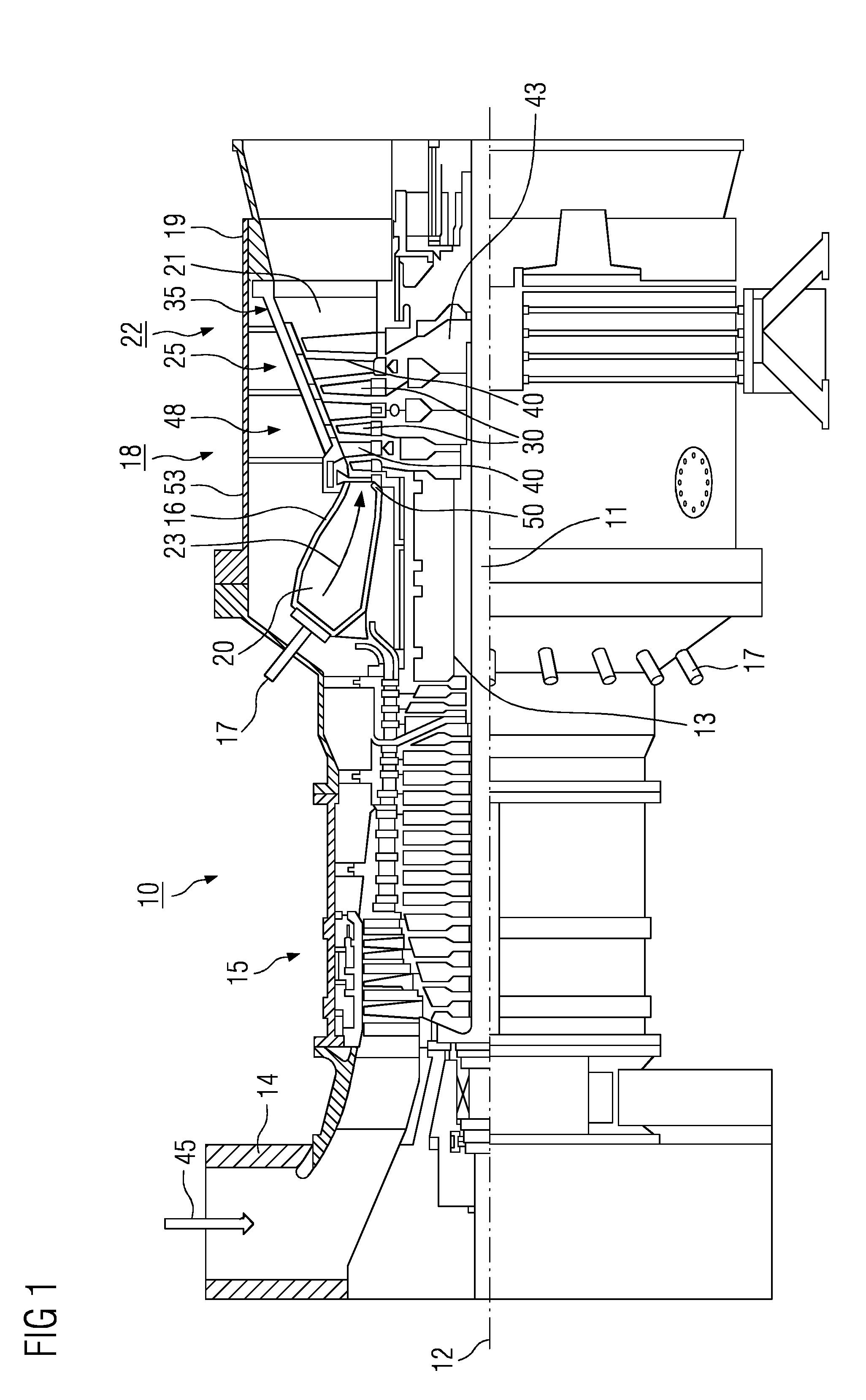
[0026]FIG. 1 is a schematic diagram of a gas turbine 10 depicting internal components. The gas turbine 10 includes a rotor 13 which is mounted such that it can rotate along an axis of rotation 12, has a shaft 11 and is also referred to as a turbine rotor.

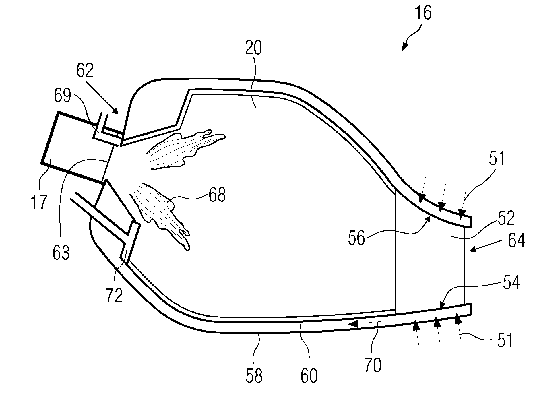
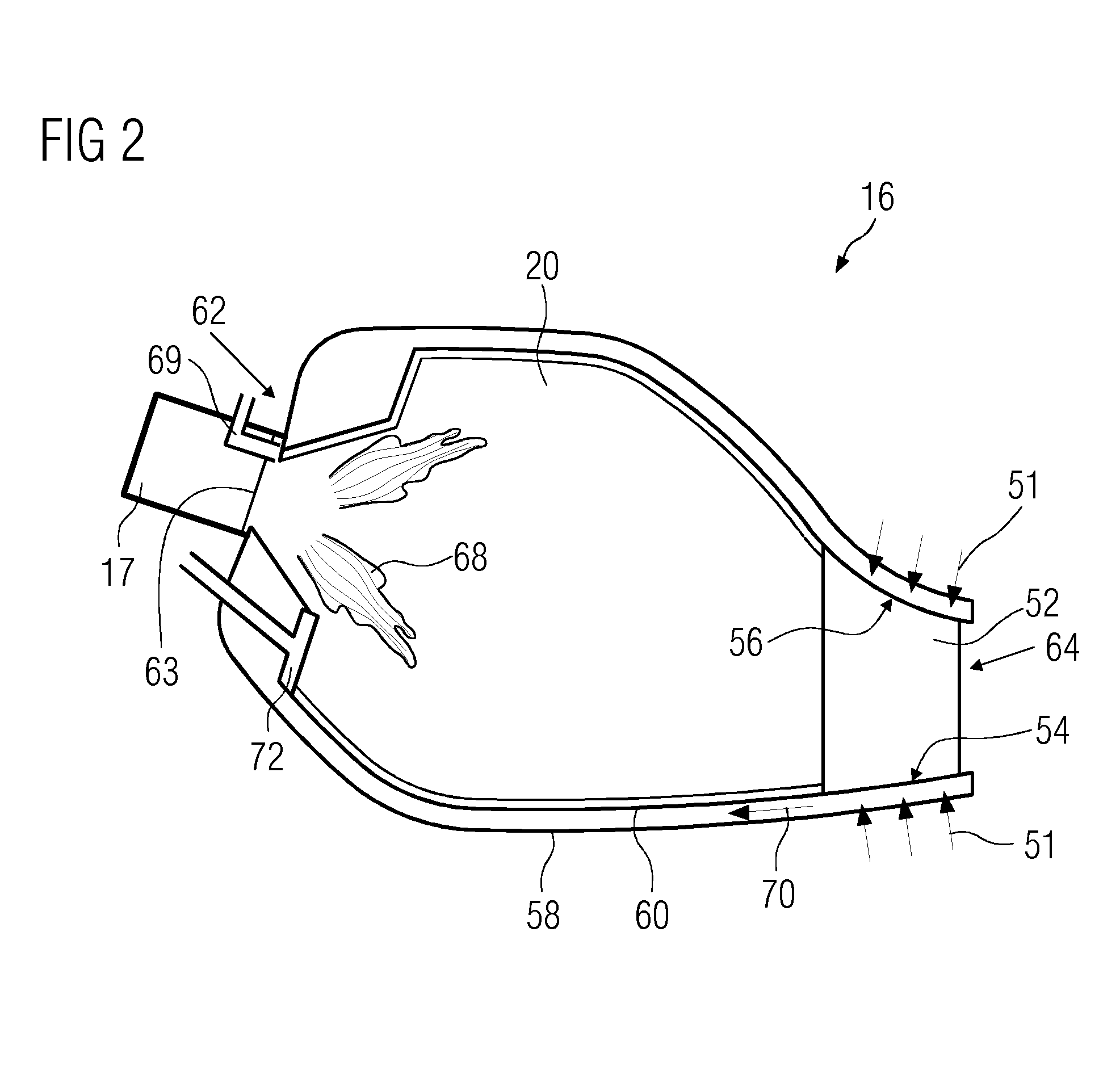
[0027]The gas turbine 10 includes an intake housing 14, a compressor 15, a combustor 16 having a combustion chamber 20, a turbine 18, and an exhaust-gas housing 19 following one another along the rotor 13. The combustion chamber 20 is an annular combustion chamber with a plurality of coaxially arranged burners 17.

[0028]The annular combustion chamber 20 is in communication with an annular hot-gas passage 21, where, by way of example, four successive turbine stages 22 form the turbine 18.

[0029]It may be noted that each turbine stage 22 is formed, for example, from two blade or vane rings. As seen in the direction of flow of a working medium 23 from the combustion chamber 20 to the turbine 18, in the hot gas passage 21 a row 25 of guid...


PUM


Abstract

A combustion chamber of a combustor for a gas turbine is provided. A combustion chamber includes a plurality of segments arranged annularly about an axis of the combustion chamber, each segment comprising a radial inner wall portion and a radial outer wall portion, a first section comprising an opening for the installation of a burner, and a second section at which at least one airfoil extends between the radial inner wall portion and radial outer wall portion of the segment.

Description

CROSS REFERENCE TO RELATED APPLICATIONS[0001]This application is the US National Stage of International Application No. PCT / EP2012 / 076604 filed Dec. 21, 2012, and claims the benefit thereof. The International Application claims the benefit of European Application No. EP12150314 filed Jan. 5, 2012. All of the applications are incorporated by reference herein in their entirety.FIELD OF INVENTION[0002]The present invention relates to a combustor and more particularly to combustion chamber of a gas turbine.BACKGROUND OF INVENTION[0003]In gas turbines, fuel is delivered from a source of fuel to a combustor where the fuel is mixed with air and ignited to produce hot combustion products which are generally known as working gases. As will be appreciated, the amount of working gas produced depends on a proper and effective mixing of the fuel and air in the combustor.[0004]DE 10 2011 000879 A1 discloses a combustor for a gas turbine. The combustor comprises a combustion chamber in which a wor...

Claims


Application Information

Patent Timeline
Patent Type & Authority Applications(United States)
IPC IPC(8): F23R3/10F23R3/00
CPCF23R3/002F23R3/10F23M9/06F23R3/16F23R2900/00014F23R2900/03043F23M20/005F23R3/50F01D9/023F23R3/44F01D9/06
Inventor HASSELQVIST, MAGNUSRUBENSDORFFER, FRANK
Owner SIEMENS ENERGY GLOBAL GMBH & CO KG
Why Eureka
Try Eureka