System and method for hot wire tig positioned heat control

Active Publication Date: 2014-12-25
LINCOLN GLOBAL INC
View PDF4 Cites 19 Cited by
  • Summary
  • Abstract
  • Description
  • Claims
  • Application Information

AI Technical Summary

Benefits of technology

[0007]In accordance with an embodiment of the present invention, a welder system is provided that includes a welding torch that includes an electrode. The system can further include a power source that creates a high intensity heat source between the electrode and a workpiece to create a puddle and a wire feeder that is connected to a supply of wel

Problems solved by technology

With orbital welding often involves limited visibility of a welding zone with lead cameras and/or trailing cameras.
In either of orbital welding systems or non-orbital welding systems, lack of fusion, among o

Method used


Image

  • System and method for hot wire tig positioned heat control
  • System and method for hot wire tig positioned heat control
  • System and method for hot wire tig positioned heat control

Examples


Embodiment Construction

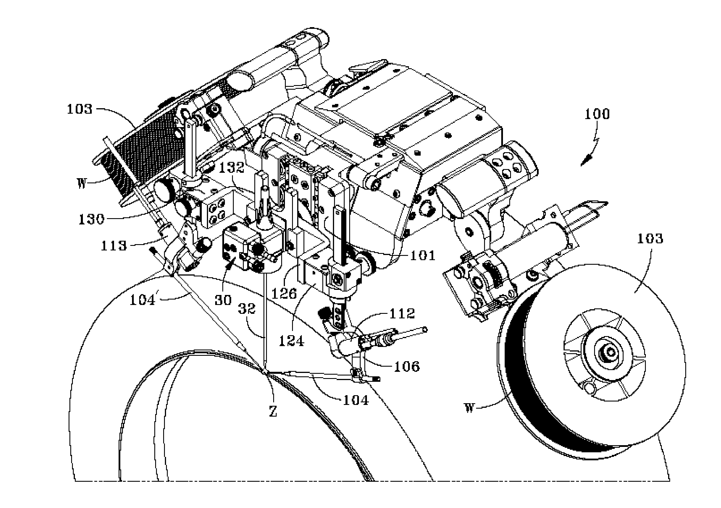
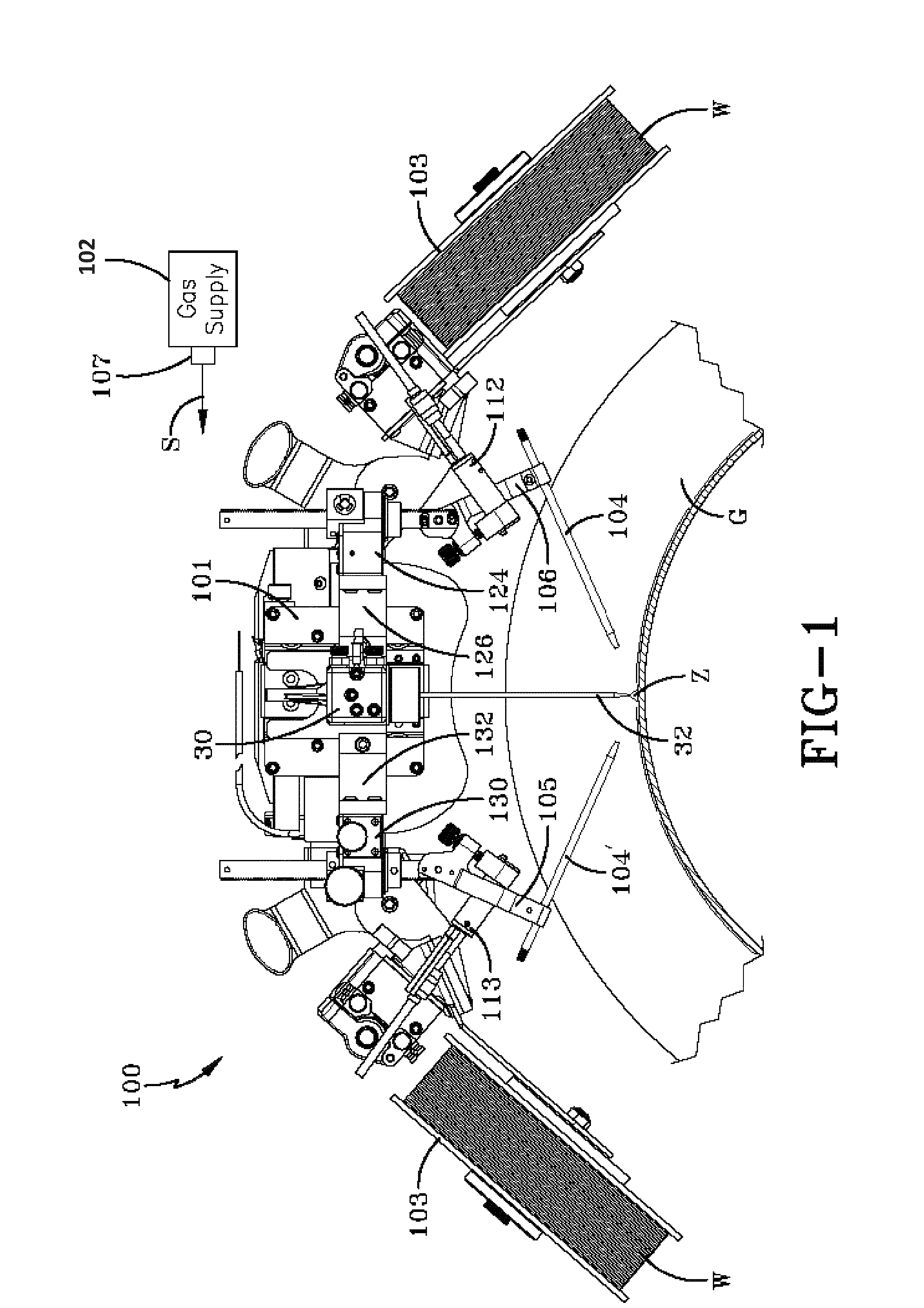
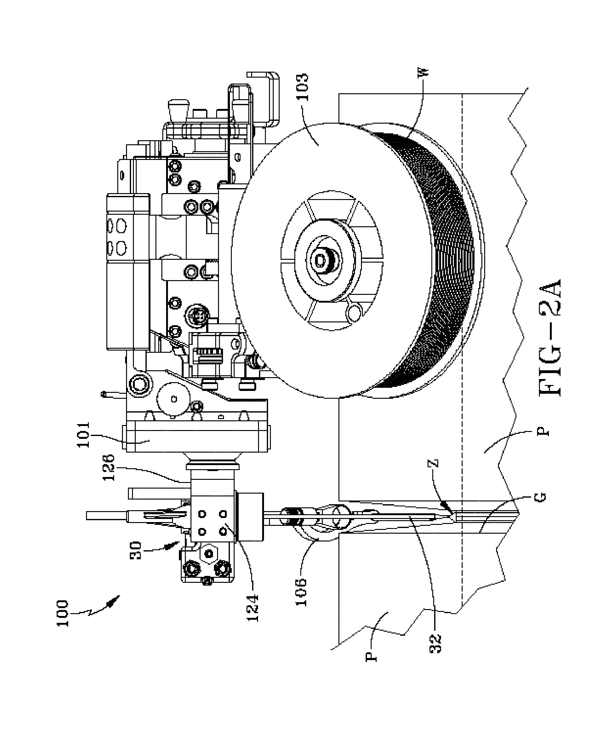
[0020]Embodiments of the invention relate to methods and systems that relate to energizing a welding wire based on a location of an electrode at an edge on a workpiece. An edge detector can be configured to identify an edge on the workpiece during a welding operation and a controller can be configured to mange a temperature of a puddle formed by the electrode by adjusting one or more welding parameters. The welding parameters can be, but are not limited to, an energizing of the welding wire, a wire feed speed, a temperature of a high intensity heat source (e.g., arc, a sub arc, a tungsten inert gas (TIG) arc, a metal inert gas (MIG) arc, a laser, a plasma arc, a metal core, or a flux core), movement speed, among others.

[0021]“Welding” or “weld” as used herein including any other formatives of these words will refer to depositing of molten material through the operation of an electric arc including but not limited to submerged arc, GMAW, MAG, MIG, TIG welding, or any electric arc use...


PUM

PropertyMeasurementUnit
Temperatureaaaaaaaaaa
Speedaaaaaaaaaa

Abstract

The invention described herein generally pertains to a system and method related to energizing a welding wire based on a location of an electrode at an edge on a workpiece. An edge detector can be configured to identify an edge on the workpiece during a welding operation and a controller can be configured to mange a temperature of a puddle formed by the electrode by adjusting one or more welding parameters. The welding parameters can be, but are not limited to, an energizing of the welding wire, a wire feed speed, a temperature of a high intensity heat source (e.g., arc, a sub arc, a tungsten inert gas (TIG) arc, a metal inert gas (MIG) arc, a laser, a plasma arc, a metal core, or a flux core), movement speed, among others

Description

PRIORITY[0001]This application claims the benefit of priority to U.S. Provisional Application Ser. No. 61 / 838,028, filed Jun. 21, 2013, and entitled “SYSTEM AND METHOD FOR HOT WIRE TIG POSITIONED HEAT CONTROL.” The entirety of the aforementioned application is incorporated herein by reference.TECHNICAL FIELD[0002]In general, the present invention relates to an orbital welding system or a non-orbital welding system. More particularly, the present invention relates to a energizing a welding wire based on a detection of an edge on a workpiece during a welding operation.BACKGROUND OF THE INVENTION[0003]Welding systems reside at the core of the modern industrial age. From massive automobile assembly operations to automated manufacturing environments, these systems facilitate joining in ever more complicated manufacturing operations. Hot wire welding processes a wire or electrode being heated (e.g., via current) and received by a puddle created by a main heat source (e.g., plasma arc, tun...

Claims


Application Information

Patent Timeline
IPC IPC(8): B23K9/095B23K26/20B23K10/02
CPCB23K9/0956B23K26/20B23K10/02B23K9/0216B23K9/0286B23K9/124B23K9/167B23K37/0217B23K37/0282B23K9/095B23K9/1006B23K9/1093
Inventor COLE, STEPHEN R.PETERS, STEVEN R.
Owner LINCOLN GLOBAL INC
Why Eureka
Try Eureka