Transmitting Unit for a Magnetic Resonance Imaging System

a technology of magnetic resonance imaging and transmitting unit, which is applied in the field of transmitting unit for magnetic resonance imaging system, can solve the problems of comparatively high hardware cost and inability to retrofit existing single-channel systems, and achieve the effect of improving measurement results and optimizing the homogenization of magnetic field

Inactive Publication Date: 2014-12-25
SIEMENS AG
View PDF2 Cites 0 Cited by
  • Summary
  • Abstract
  • Description
  • Claims
  • Application Information

AI Technical Summary

Benefits of technology

[0008]The present embodiments may obviate one or more of the drawbacks or limitations in the related art. For example, a transmitting unit for a magnetic resonance imaging system that allows a high flexibility in the use of a plurality of local coils with an individual amplifier is provided.
[0009]A connectable phase shifter is arranged between the power splitter and at least one of the transmitting coils to allow the high flexibility.
[0010]One or more of the present embodiments are based on the consideration that the comparatively low flexibility of local coils connected by a power splitter is caused by the fact that in a power splitter, a fixed phase and the same amplitude is assigned to each channel. This may be remedied with a genuine multi-channel system with an RFPA and a signal generating unit for each individual channel. However, this produces a comparatively high outlay with respect to hardware. Existing single-channel systems may not be retrofitted. In order to achieve an individual adjustment of the channels emerging from a power splitter despite an individual RFPA, a phase shifter is assigned to the channels (e.g., to all channels apart from one). The phase shifter may be configured such that the phase shifter may be connected individually. An optimization of the homogeneity of the magnetic field is made possible as a result.
[0015]In a further advantageous configuration, the transmitting unit is configured to drive the respective phase shifter and / or the respective damping element based on operating parameters of the respectively connected transmitting coil. The operating parameters for the transmitting and receiving mode of the coil may be stored in the coil file in the coil and may be read out by the central control unit of the MRI system. Depending on these operating parameters, the phases and amplitudes of the transmission signals may be set in relation to the respective local coils, such that an optimization of the homogeneity of the magnetic field is achieved.
[0020]The advantages achieved by one or more of the present embodiments includes, for example, that the introduction of connectable phase shifters and / or damping elements into the output channels of a power splitter in an MRI system makes an individual setting of the channels in relation to the individual transmitting coils possible with regard to phase and amplitude, even though the system includes fewer amplifiers than transmitting coils. As a result, an optimization of the homogenization of the magnetic field is achieved, which improves the measurement results.

Problems solved by technology

However, this produces a comparatively high outlay with respect to hardware.
Existing single-channel systems may not be retrofitted.

Method used


Image

  • Transmitting Unit for a Magnetic Resonance Imaging System
  • Transmitting Unit for a Magnetic Resonance Imaging System
  • Transmitting Unit for a Magnetic Resonance Imaging System

Examples


Embodiment Construction

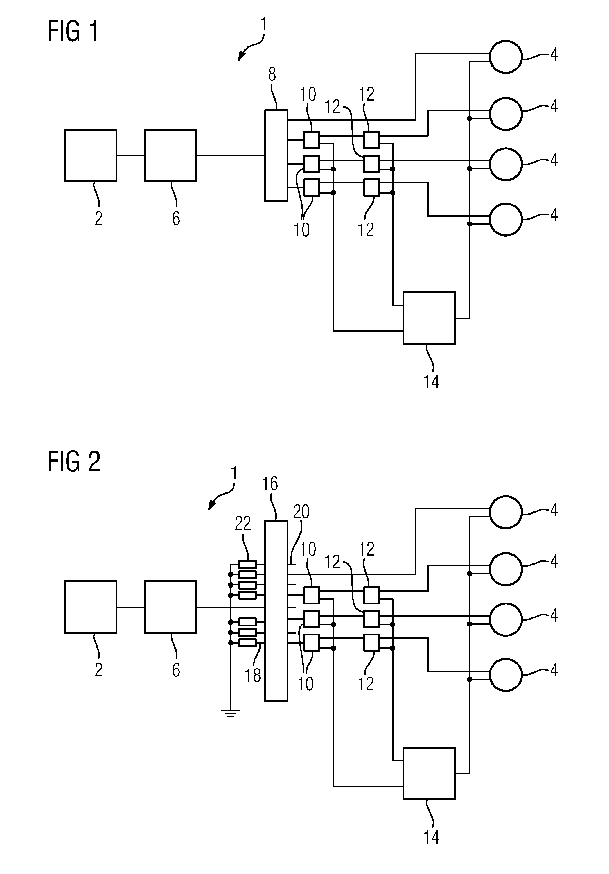
[0024]FIG. 1 schematically shows one embodiment of a transmitting unit 1 in a magnetic resonance imaging system 24, which is also described below in FIG. 3. A signal generating unit 2 and four electrically decoupled transmitting coils 4 designed as local coils are shown.

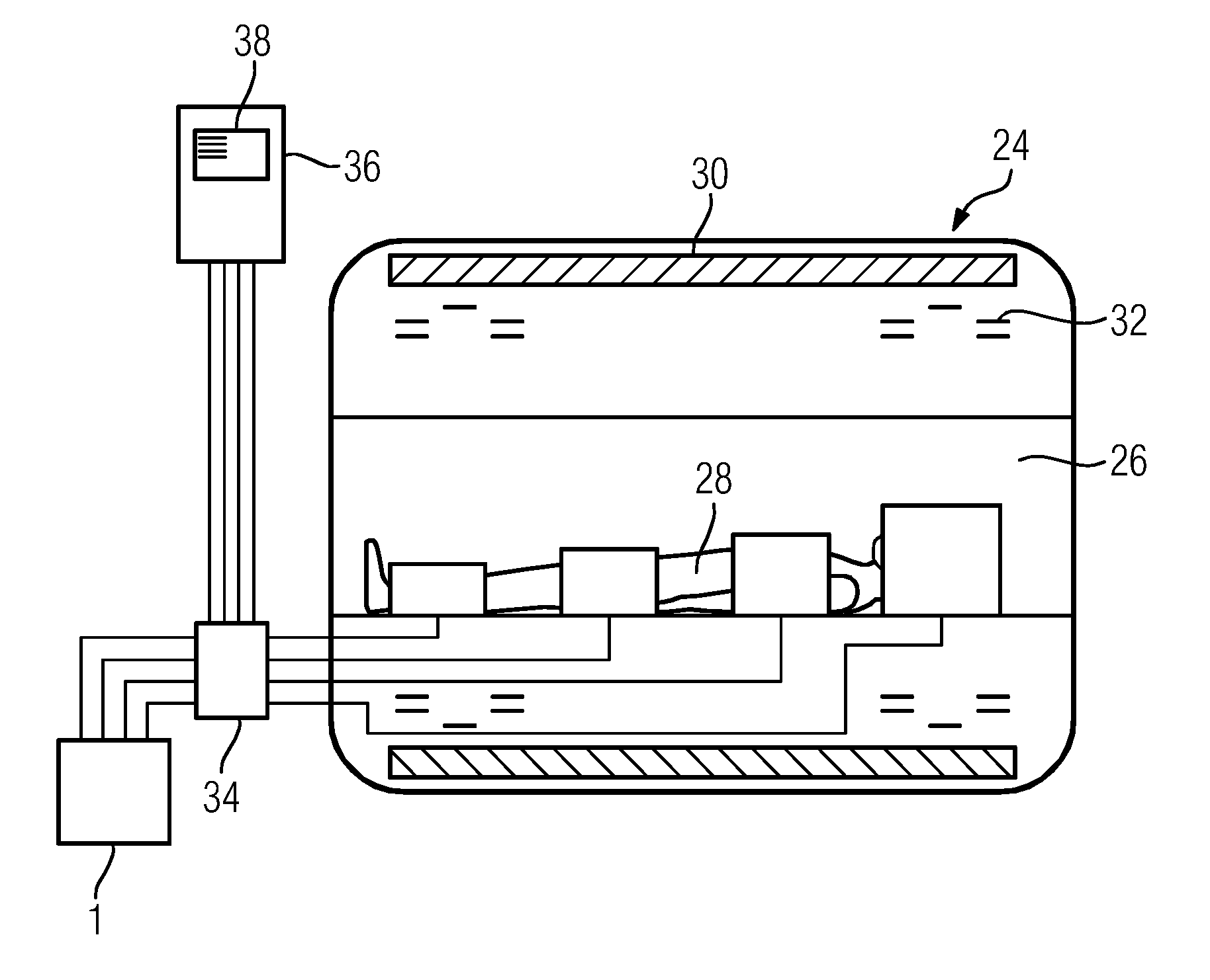
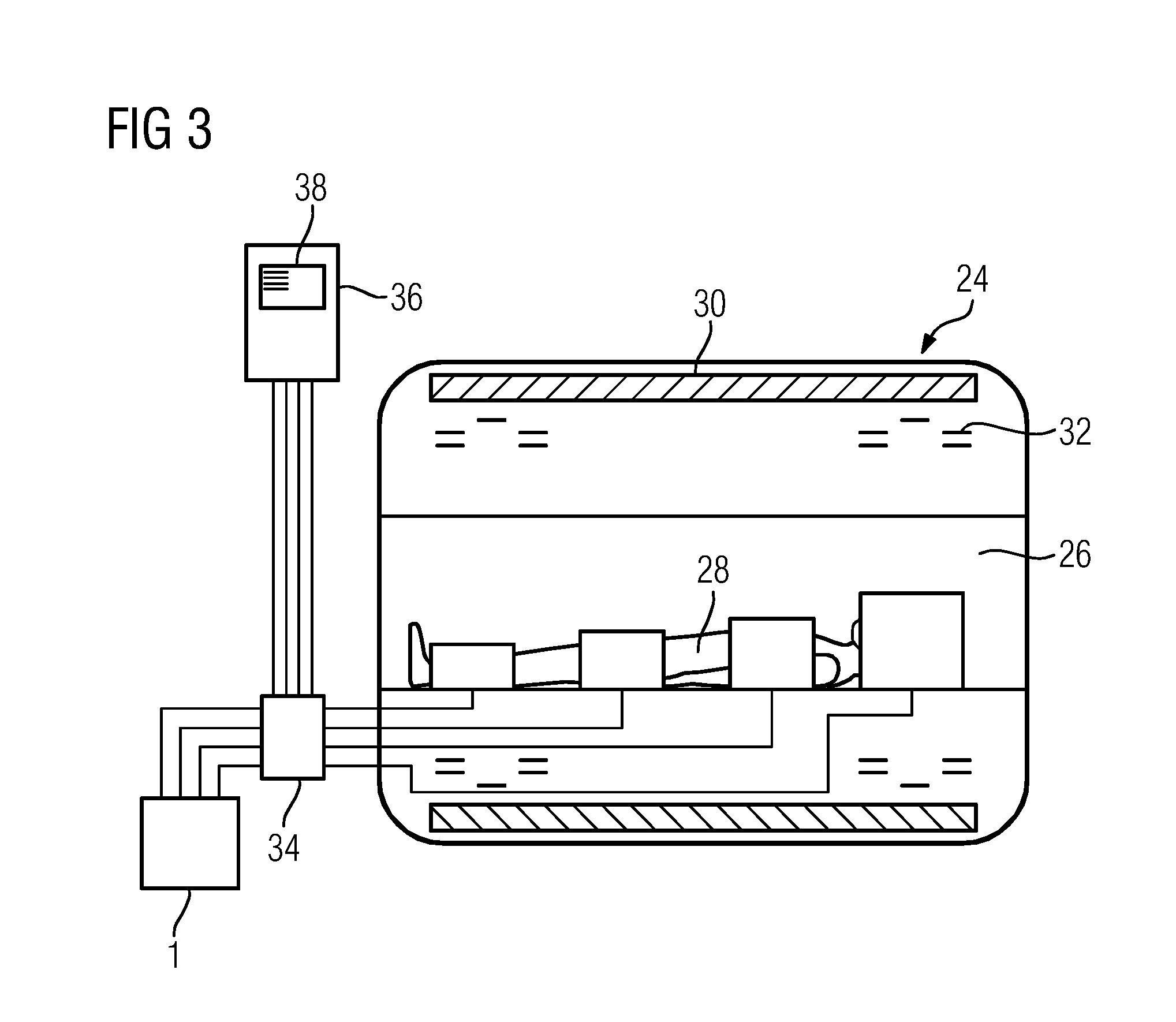
[0025]Further parts of the magnetic resonance imaging system 24 are shown schematically in section in FIG. 3. A patient 28 arranged in a cylindrical tunnel 26 is enclosed by a strong magnet 30, which generates a magnetic field of, for example, 7 teslas. Gradient coils 32, which likewise enclose the patient 28 in different axial regions and may superimpose gradient fields, are also provided. The gradient coils 32 are also driven by the transmitting unit 1, this not being graphically illustrated for the sake of clarity. The four transmitting coils 4 are arranged at the patient. The principle of the MRI measurement is explained briefly below.

[0026]The actual measurement takes place according to the principle of the spin...


PUM

PropertyMeasurementUnit
magnetic fieldaaaaaaaaaa
capacitanceaaaaaaaaaa
magnetic fieldaaaaaaaaaa

Abstract

A transmitting unit for a magnetic resonance imaging system includes a signal generating unit, an amplifier connected downstream of the signal generating unit, a power splitter connected downstream of the amplifier, and a plurality of electrically decoupled transmitting coils connected downstream of the power splitter. A connectable phase shifter is arranged between the power splitter and at least one transmitting coil of the plurality of electrically decoupled transmitting coils.

Description

[0001]This application claims the benefit of DE 10 2013 211 842.2, filed on Jun. 21, 2013, and DE 10 2013 213 400.2, filed on Jul. 9, 2013, which are hereby incorporated by reference in their entirety.BACKGROUND [0002]The present embodiments relate to a transmitting unit for a magnetic resonance imaging system.[0003]Magnetic resonance imaging (MRI) may be used to generate slice images of the human or animal body that allow an assessment of the organs and many pathological organ changes. MRI is based on very strong magnetic fields and alternating magnetic fields in the radio-frequency range (e.g., generated in an MRI) that resonantly excite specific atomic nuclei (e.g., the hydrogen nuclei / protons) in the body, as a result of which an electrical signal is induced in a receiver circuit.[0004]MRI systems may have a transmitting unit that is provided for generating a substantially homogeneous radio-frequency field for exciting the nuclear spins. In this case, the associated transmitting...

Claims


Application Information

Patent Timeline
Patent Type & Authority Applications(United States)
IPC IPC(8): G01R33/38G01R33/00
CPCG01R33/0052G01R33/38G01R33/3607G01R33/5612G01R33/5659Y10T29/49002
Inventor MATSCHL, VOLKER
Owner SIEMENS AG
Why Eureka
Try Eureka