
Performing Image Rejection On Bandpass Signals

a bandpass signal and image technology, applied in the direction of digital transmission, amplitude demodulation details, transmission, etc., can solve the problems of image interference cross-talk and reception unacceptabl

Active Publication Date: 2014-12-25
SILICON LAB INC
View PDF10 Cites 7 Cited by
  • Summary
  • Abstract
  • Description
  • Claims
  • Application Information

AI Technical Summary

Benefits of technology

The patent describes an apparatus and method for improving image rejection in a receiver. The apparatus includes a signal channel path with filters to downconvert RF signals to complex intermediate frequencies (IF) and an image rejection calibration circuit to remove mismatch information. The calibration circuit includes filters and combiners to combine the in-phase and quadrature portions of the complex IF signal. A correlator is also included to detect and prevent unintended correlations between desired and interferer channels. The technical effects of this patent include improved image rejection, reduced interference, and improved signal quality.

Problems solved by technology

In a typical low-IF receiver architecture, mismatch between in-phase and quadrature phase paths cause image interference cross-talk.
In many receivers, one or more strong adjacent channels may become the image interference and make reception unacceptable.

Method used


Image

  • Performing Image Rejection On Bandpass Signals
  • Performing Image Rejection On Bandpass Signals
  • Performing Image Rejection On Bandpass Signals

Examples


Embodiment Construction

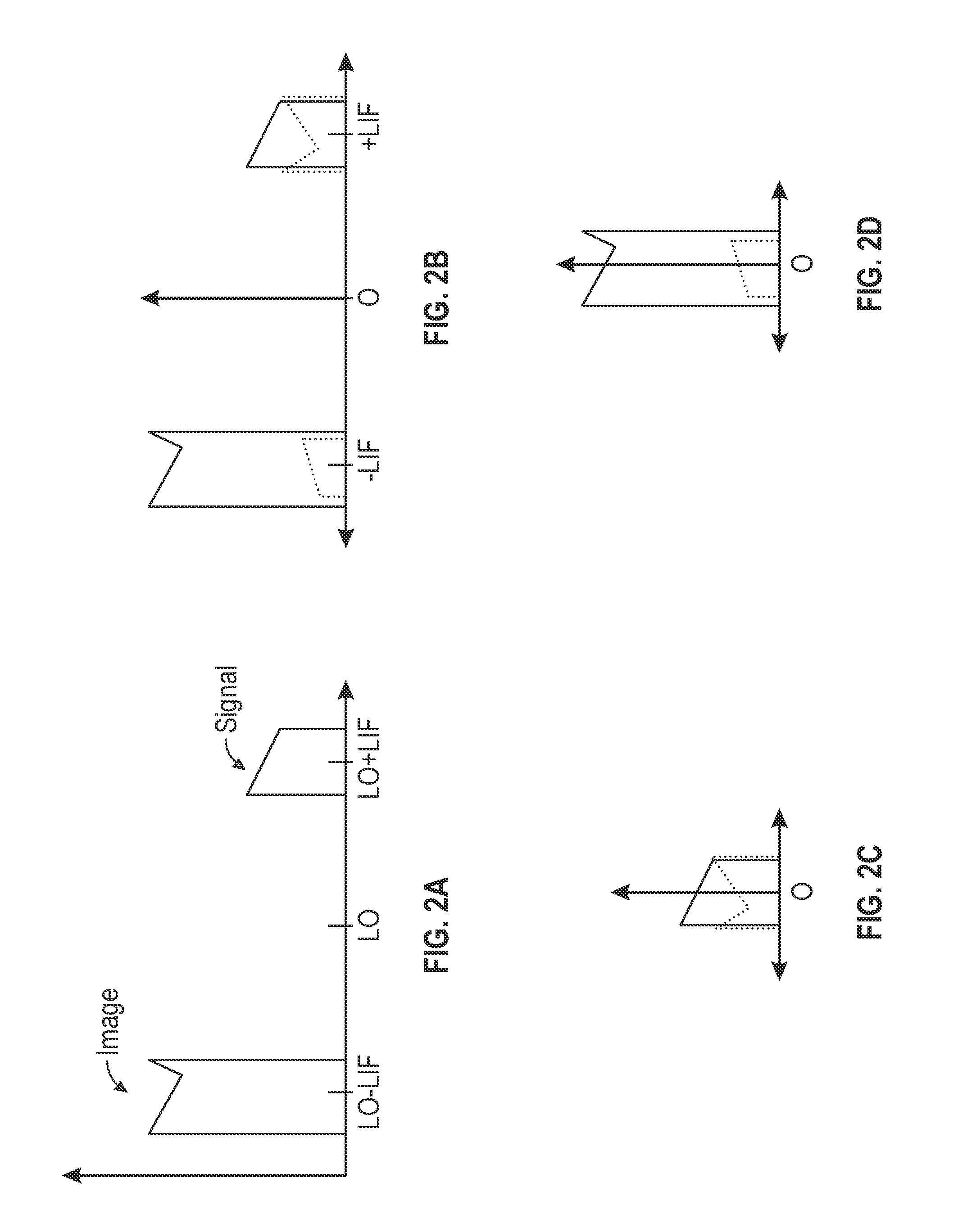
[0020]Due to mismatches in an analog front end of a receiver having a complex signal path (i.e., in-phase (I) and quadrature-phase (Q) paths), part of an interference (e.g., image) signal may be within a desired signal band (and vice-versa). Embodiments seek to remove the interference signal from contaminating the desired signal. More specifically, adaptive finite impulse response (FIR) filters can remove the residuals from a signal processing path.

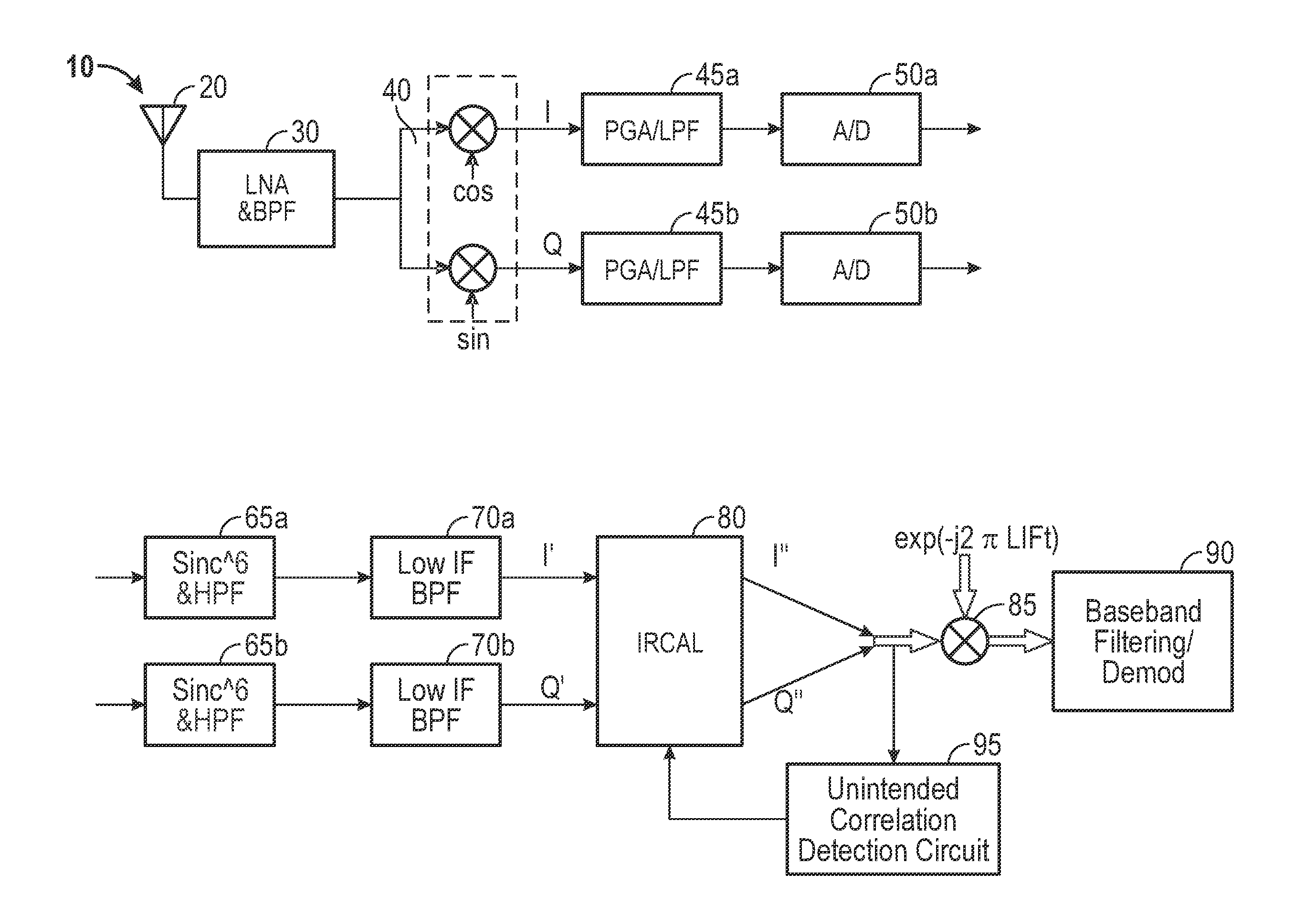
[0021]A high level architecture of a receiver in accordance with one embodiment is shown in FIG. 1. As shown in FIG. 1, receiver 10 includes an analog signal path and a digital signal path. In various embodiments, the digital signal path may be implemented using a digital signal processor (DSP). Furthermore, both the analog and digital portions may be implemented in a single integrated circuit, e.g., a single die CMOS circuit, although other circuits are possible.

[0022]As seen, incoming signals, which may be RF signals received over the a...


PUM


Abstract

An image rejection (IR) circuit is configured to receive a complex signal from a radio frequency (RF) mixer, where the complex signal includes an in-phase signal portion and a quadrature signal portion. This IR circuit may include: an in-phase path to remove first mismatch information from the in-phase signal portion and associated with at least one in-phase multi-tap filter; a quadrature path to remove second mismatch information from the quadrature signal portion and associated with at least one quadrature multi-tap filter; and a correlation unit to independently update each of the multiple taps of the in-phase multi-tap filter and the quadrature multi-tap filter according to a priority scheme.

Description

BACKGROUND[0001]Many receivers, both radio and television, include an in-phase / quadrature (I / Q) demodulation architecture, in which a received modulated carrier signal is simultaneously applied to an I-channel mixer and a Q-channel mixer. A local oscillator (LO) is also applied to the mixers to effect frequency conversion from a radio frequency (RF) at which the radio signal is received to an intermediate frequency (IF). In an I / Q demodulator, the LO signal that is applied to this Q-channel mixer is offset by 90° from the LO signal that is applied to the I-channel mixer.[0002]Image rejection is one metric by which receiver system performance may be evaluated. In general, image rejection refers to the ability of the receiver to reject responses resulting from RF signals at a frequency offset from the desired RF carrier frequency by an amount equal to twice the IF of a superheterodyne receiver. For example, if the desired RF signal is at 100 megahertz (MHz), and the receiver IF is 4 M...

Claims


Application Information

Patent Timeline
Patent Type & Authority Applications(United States)
IPC IPC(8): H03D1/04
CPCH03D1/04H03D7/165H03D7/18
Inventor KHOURY, JOHNZHOU, YAN
Owner SILICON LAB INC
Learn More