Gas lift system for oil production

Inactive Publication Date: 2015-01-01
CALTEC
View PDF5 Cites 6 Cited by
  • Summary
  • Abstract
  • Description
  • Claims
  • Application Information

AI Technical Summary

Benefits of technology

This patent describes an improved gas lift system for use in a well and a method to increase production by reducing the pressure at the wellhead. A boosting unit, called a surface jet pump, is used at surface to reduce the pressure and increase the flow of gas through the well. This invention is a cost-effective and simple solution to improve well production.

Problems solved by technology

These so-called erratic flow regimes cause a significant loss of pressure within the well bore and result in an increase in the flowing bottom hole pressure (FBHP) and build up of liquids because of the low velocity of gas to lift the liquids.
A rise in the FBHP will in turn restrict production.
There are, however, the following conditions that can arise in a gas lift system:There is insufficient amount of lift gas available at the desired pressure to achieve the maximum or optimum level of reduction in the hydrostatic head of fluids and the reduction in the FBHP for achieving maximum production.The high pressure (HP) gas is not of sufficient pressure to inject it at the lowest parts of the well bore where gas lift is needed and is more effective.The tubing size restricts the amount of lift gas as excessive frictional losses may be experienced, negating the benefit of lift gas.
The above mentioned scenarios restrict production and in some cases could lead to a build up of liquids within the well bore, resulting in erratic production and final seizure of production as the reservoir pressure drops with time.

Method used


Image

  • Gas lift system for oil production
  • Gas lift system for oil production
  • Gas lift system for oil production

Examples


Embodiment Construction

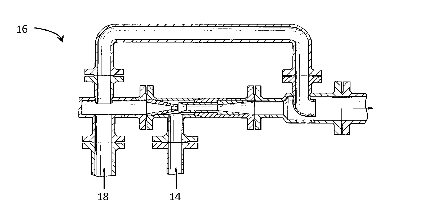
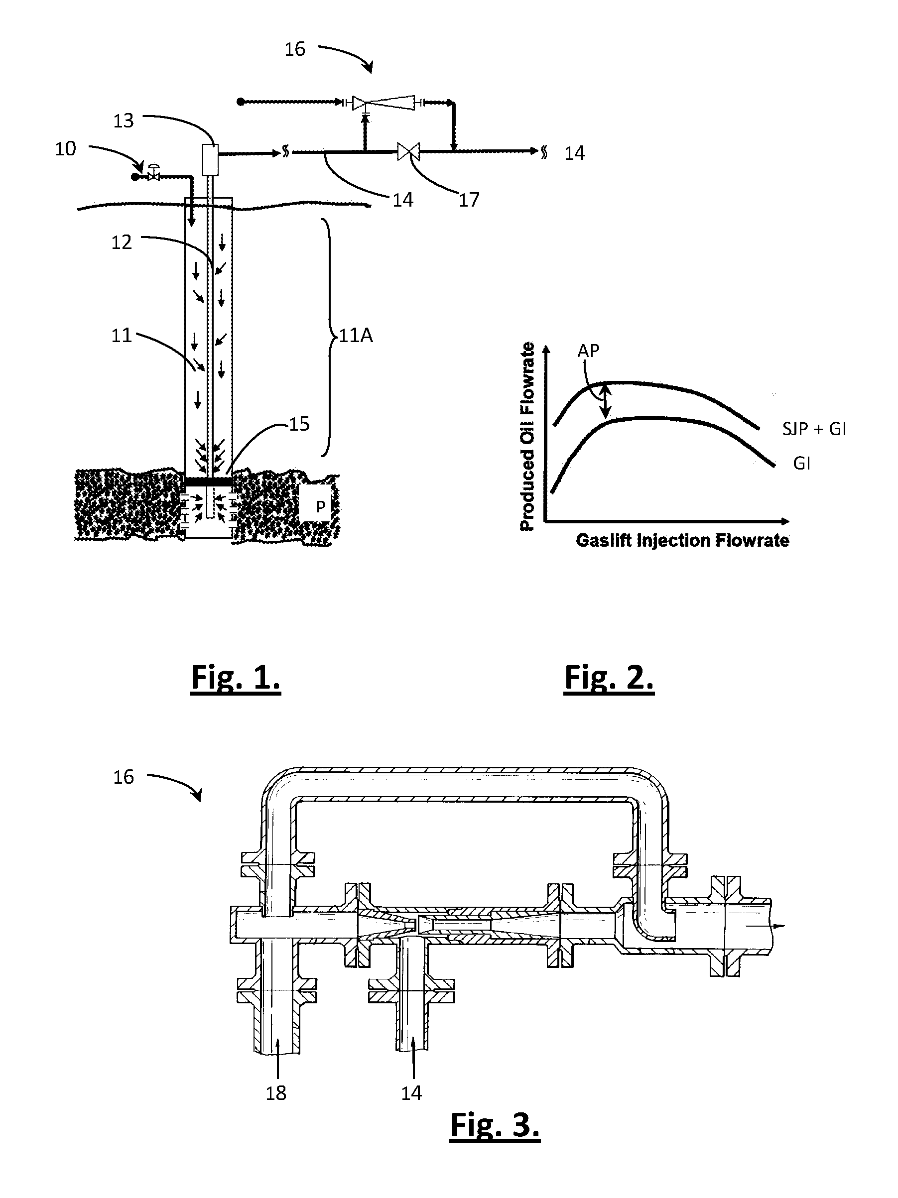
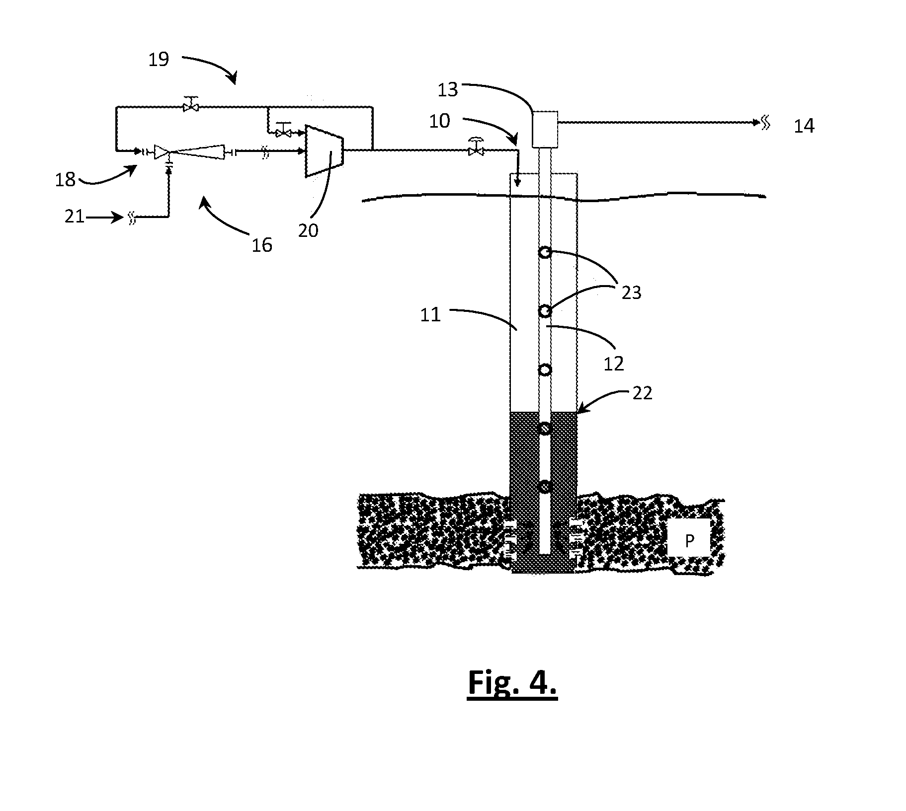
[0032]Referring to FIG. 1, increased oil production in a low GOR well is achieved by implementing a gas lift injection system 10 into a well 11 such that the hydrostatic head of fluids in the extraction tube 12 is reduced. An oil / gas mixture leaves the well head 13 for downstream processing via a pipeline 14.

[0033]According to known practice, a pressurized upper section 11A of the well 11 is sealed from the pay zone P by a barrier 15 (through which the tube 12 passes) and gas is introduced through the tube 12 wall at different depths via valves or apertures (not pictured in FIG. 1). The flow rate of fluid naturally rising through the tube 12 due to underground pressure in the pay zone P is increased by bubbles forming from the injected gas into the tube 12.

[0034]The gas lift system as described above is generally known; however, in many cases there may be an insufficient amount of lift gas available at the desired pressure to achieve the maximum or optimum level of reduction in the ...


PUM


Abstract

An improved gas lift system for use in oil production from a well bore (11) utilising a gas lift injection (10) system of the known type and further including a surface jet pump (16) downstream of the well head (13) for reducing the flowing well head pressure and capable of discharging produced fluid (14) at a pressure required by a downstream production system.

Description

CROSS-REFERENCE TO RELATED APPLICATIONS[0001]This application claims foreign priority benefits under 35 U.S.C. §119(a)-(d) to GB1202904.7 filed Feb. 20, 2012, GB1210847.8 filed 19 Jun. 2012 and PCT / GB2013 / 050321 filed 13 Feb. 2013, which are incorporated by reference in their entirety.BACKGROUND OF THE INVENTION[0002]1. Field of the Invention[0003]The present invention relates to a gas lift system for improving oil production from a well.[0004]2. Description of Related Art[0005]The use of gas lift, involving the injection of high pressure gas at different depths of an oil well, is well known as an effective way to reduce the hydrostatic head of fluids flowing through the well bore and to increase the velocity of flow in order to prevent liquids building up in the well bore.[0006]In a typical oil production case, particularly when the gas oil ratio (GOR) of the produced fluids is low (typically below 500 Scf / bbl / day) the flow regime of the produced fluids varies within the well bore,...

Claims


Application Information

Patent Timeline
IPC IPC(8): E21B43/12
CPCE21B43/124E21B43/123E21B43/122E21B43/126
Inventor BEG, MIRZA NAJAM ALISARSHAR, MIR MAHMOOD
Owner CALTEC
Why Eureka
Try Eureka