Multi-pair differential signal transmission cable

a signal transmission cable and differential signal technology, applied in the direction of power cables, cables, insulated conductors, etc., can solve the problems of crosstalk and degrade the efficiency of signal transmission, and achieve the effect of suppressing leakage of common mode energy and reducing orientation changes

Active Publication Date: 2015-01-01
HITACHI METALS LTD
View PDF26 Cites 23 Cited by
  • Summary
  • Abstract
  • Description
  • Claims
  • Application Information

AI Technical Summary

Benefits of technology

[0021]Thus, even when the plurality of differential signal transmission cables are twisted and bundled together, since the transverse cross-section of the first intervening member is held in a circular shape by the second intervening members, it is possible to reduce changes in orientation of each of the differential signal transmission cables, flattening and deformation of the insulator, and occurrence of electrical imbalance.
[0022]Since each of the overlap portions where a large amount of common mode current flows is oriented toward the covering member, it is possible to suppress leakage of common mode energy toward the inside of the multi-pair differential signal transmission cable.
[0023]Therefore, a multi-pair differential signal transmission cable capable of suppressing the occurrence of crosstalk can be obtained.

Problems solved by technology

However, in the multi-pair differential signal transmission cable disclosed in the document described above, the efficiency of signal transmission may be degraded by crosstalk between differential signal transmission cables.
In practice, however, current (common mode current) flowing through the shielding tape conductor generates a magnetic field, and the resulting common mode component also causes the occurrence of crosstalk.
The common mode current is also generated by electrical imbalance between differential signal transmission cables.

Method used


Image

  • Multi-pair differential signal transmission cable
  • Multi-pair differential signal transmission cable
  • Multi-pair differential signal transmission cable

Examples


first embodiment

[0032]the present invention will now be described in detail with reference to the drawings.

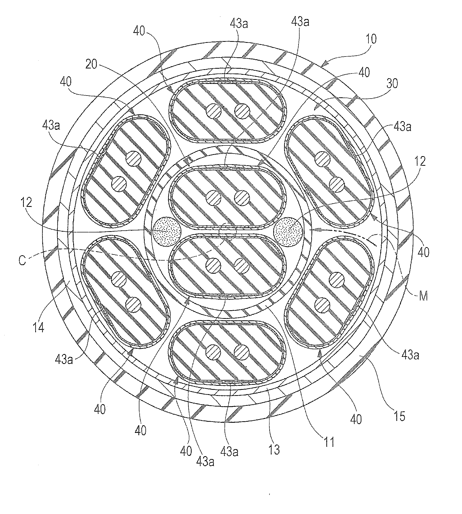
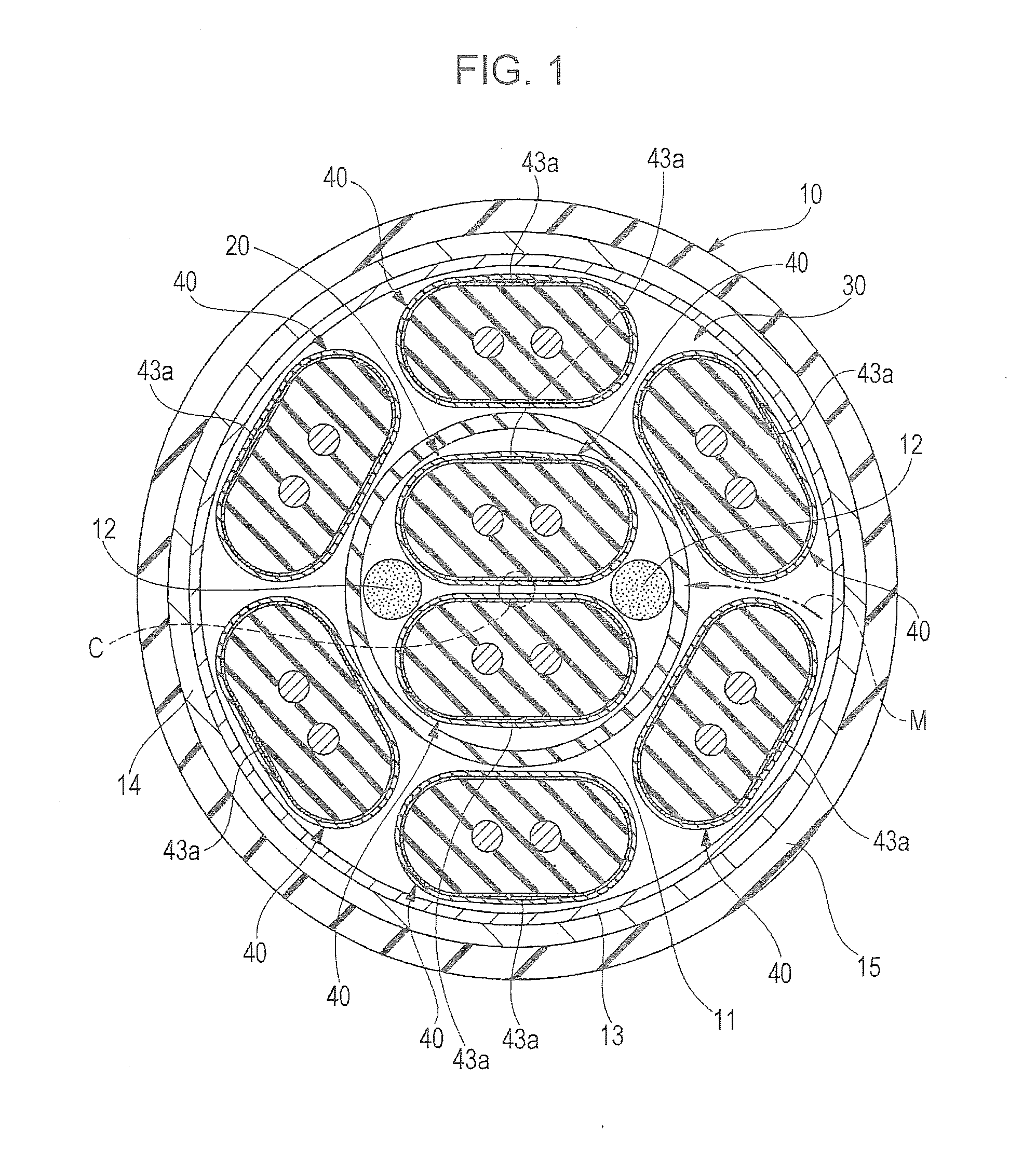
[0033]FIG. 1 is a transverse cross-sectional view of a multi-pair differential signal transmission cable according to the first embodiment, FIG. 2A is a perspective view of a differential signal transmission cable according to the first embodiment, and FIG. 2B is a cross-sectional view of the differential signal transmission cable according to the first embodiment.

[0034]As illustrated in FIG. 1, a multi-pair differential signal transmission cable 10 according to the first embodiment is circular in transverse cross-section. The multi-pair differential signal transmission cable 10 includes a first cable assembly 20 disposed around an axial center C (indicated by a dashed circle in FIG. 1), and a second cable assembly 30 disposed around the first cable assembly 20.

[0035]The first cable assembly 20 is formed by twisting two differential signal transmission cables 40. The second cable assembly 30 i...

third embodiment

[0071]FIG. 7A is a cross-sectional view of a differential signal transmission cable according to the

[0072]As illustrated in FIG. 7A, a differential signal transmission cable 70 that forms a multi-pair differential signal transmission cable according to the third embodiment differs from the differential signal transmission cable 60 of the second embodiment in that the differential signal transmission cable 70 includes an insulator 71 made of foamed polyethylene containing air bubbles, and an insulating skin layer 72 between the insulator 71 and the first shielding tape conductor 43. The insulating skin layer 72 is made of an insulating material, such as polytetrafluoroethylene (PTFE), and has a substantially cylindrical shape. For example, during extrusion molding of the insulator 71, the insulating skin layer 72 holds the insulator 71 so as to prevent deformation of the insulator 71 which is soft and has not yet hardened.

[0073]The third embodiment also differs from the second embodi...

fourth embodiment

[0076]FIG. 7B is a cross-sectional view of a differential signal transmission cable according to the

[0077]As illustrated in FIG. 7B, a differential signal transmission cable 80 that forms a multi-pair differential signal transmission cable according to the fourth embodiment differs from the differential signal transmission cable 40 of the first embodiment in that the signal line conductors 41 are individually covered with respective insulators 81 and 82. This makes an intercentral distance P2, which is a distance between the axial centers of the signal line conductors 41, greater than the intercentral distance P1 in the first to third embodiments described above (P2>P1).

[0078]In the fourth embodiment, a length dimension D2 of the overlap portion 43a of the first shielding tape conductor 43 along the direction of arrangement of the signal line conductors 41 is set to be greater than the length dimension D1 in the first to third embodiments described above (D2>D1). To prevent a large ...


PUM

PropertyMeasurementUnit
distanceaaaaaaaaaa
aspect ratioaaaaaaaaaa
dielectric constantaaaaaaaaaa

Abstract

A pair of second intervening members configured to hold a transverse cross-section of a first intervening member in a circular shape is disposed inside the first intervening member together with a first cable assembly. An overlap portion of each of differential signal transmission cables that form the first cable assembly and a second cable assembly is oriented toward a second shielding tape conductor.

Description

[0001]The present application is based on Japanese patent application No. 2013-134041 filed on Jun. 26, 2013, the entire contents of which are incorporated herein by reference.BACKGROUND OF THE INVENTION[0002]1. Field of the Invention[0003]The present invention relates to a multi-pair differential signal transmission cable formed by bundling together a plurality of differential signal transmission cables.[0004]2. Description of the Related Art[0005]Devices (e.g., servers, routers, and storage products) that deal with high-speed digital signals of several gigabits per second (Gbit / s) or more have adopted a differential interface standard, such as the low-voltage differential signaling (LVDS). Between devices or between circuit boards within a device, differential signals are transmitted through a differential signal transmission cable. Differential signals are characterized by having a high resistance to external noise while realizing a low-voltage system power supply.[0006]A differe...

Claims


Application Information

Patent Timeline
Patent Type & Authority Applications(United States)
IPC IPC(8): H01B11/08
CPCH01B11/085H01B11/20H01B11/002
Inventor NONEN, HIDEKISUGIYAMA, TAKAHIRO
Owner HITACHI METALS LTD
Why Eureka
Try Eureka