Keycap, key structure and keyboard

a key cap and key structure technology, applied in the field of key cap and key structure, can solve the problems of downward movement of the key cap, process also generates unpleasant noise, damage to the key base and the key cap, etc., to achieve the effect of reducing the noise of the keyboard, and increasing the comfort of us

Active Publication Date: 2015-01-01
GIGA BYTE TECH CO LTD
View PDF11 Cites 11 Cited by
  • Summary
  • Abstract
  • Description
  • Claims
  • Application Information

AI Technical Summary

Benefits of technology

[0011]The keyboard includes a main board, and a plurality of key structures. The main board includes a plurality of cavities. The key structures are located in the said cavities. Each of the key structures includes a key switch, and a key cap. The key switch includes a key base, a resilient member, and a shaft. The key base includes a contact surface. The resilient member is positioned in the key base. The shaft is positioned on the resilient member and is able to be moved forward and back between an operating position and a releasing position relative to the key base. The shaft stays at the releasing position, and presses the resilient member while at the operating position. The key cap is placed on the shaft, and is spaced apart with the contact surface of the key base. The key cap includes a cushion member. The cushion member is positioned at one side of the key cap facing the contact surface. When the shaft is located at the operating position, the cushion member abuts on the contact surface and maintains resilience against the contact surface. Accordingly, a key cap with a cushion member is disclosed for preventing punching or crashing from the key cap and the key base, so as to absorb the force because of the material characters of the cushion member. In this way, the noise of the keyboard can be minimized, and the comfort of use can be increased, allowing the uses of these keyboards in various environments.

Problems solved by technology

However, when the user presses the key, the spring of the cap and the downward movement of the key cap produce a noise as it crashes into the key base.
Due to this movement, the key base and the key cap sustain damage and may become inoperable overtime.
Furthermore, the process also generates an unpleasant noise.
The noise interferes with the work of users and may also affect others in the vicinity.
Hence, it is not convenient to use this type of keyboard in a quiet environment such as an office or a library.

Method used


Image

  • Keycap, key structure and keyboard
  • Keycap, key structure and keyboard
  • Keycap, key structure and keyboard

Examples


first embodiment

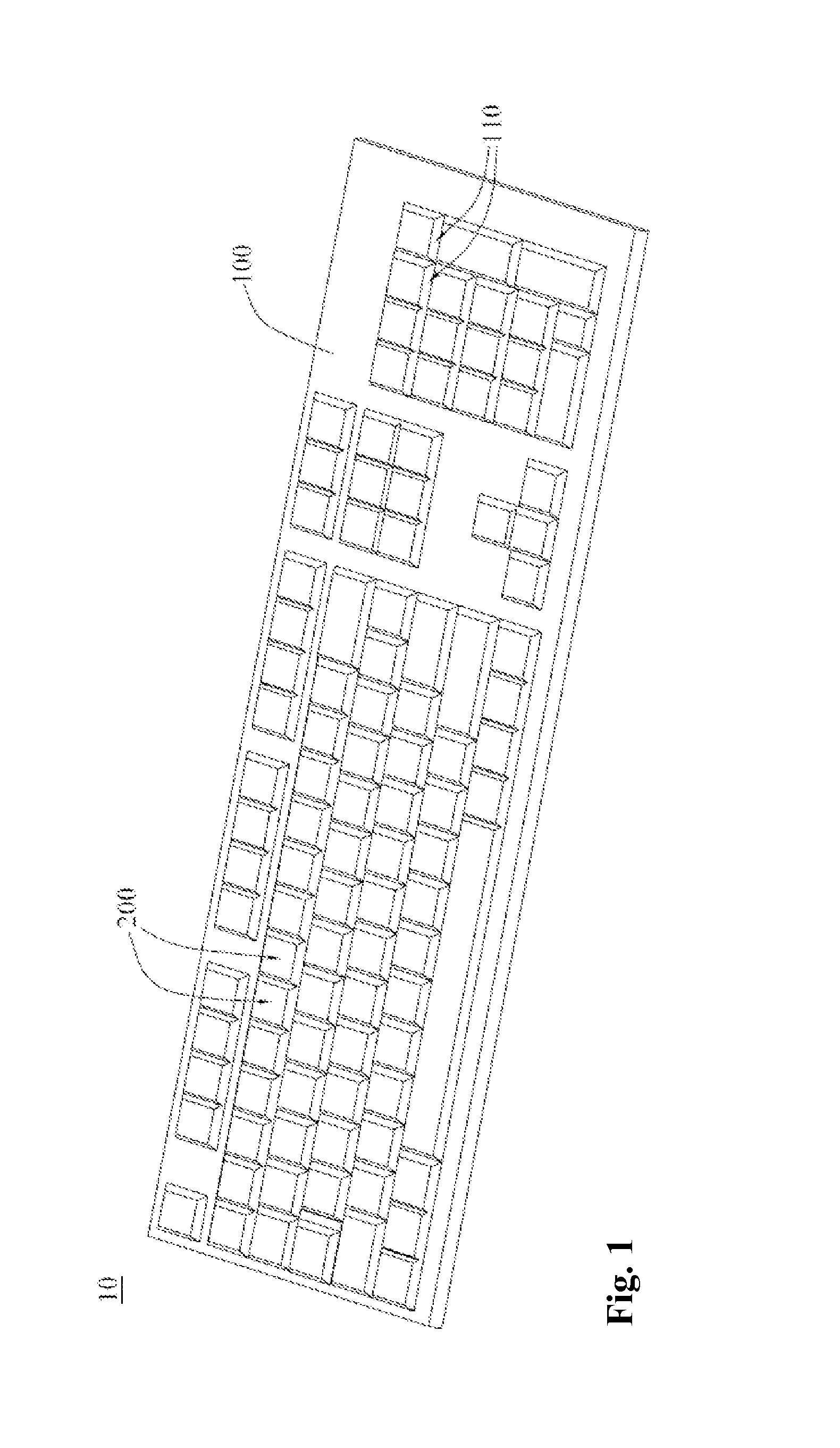
[0021]The keyboard 10 is in accordance with the first embodiment and includes a main board 100 and a plurality of key structures 200. The main board 100 includes a plurality of cavities 110. Each of the key structures 200 couples to each of the cavities 110 so as to detachably engage with the main board 100. Each of the key structures 200 includes a key switch 210 and a key cap 220. The key cap 220 is detachably engaged on the key switch 210.

[0022]More specifically, the key switch 210 of the first embodiment includes a key base 211, a resilient member 212 and a shaft 213. The key base 211 includes a contact surface 2111 and a space. The space is defined inside the key base 211. An opening of the space is formed at the contact surface 2111. The resilient member 212 and the shaft 213 couple to the space of the key base 211 through the opening respectively.

[0023]The shaft 213 is positioned onto the resilient member 212, or in non-pressing situation stays at a releasing position P1 rela...

second embodiment

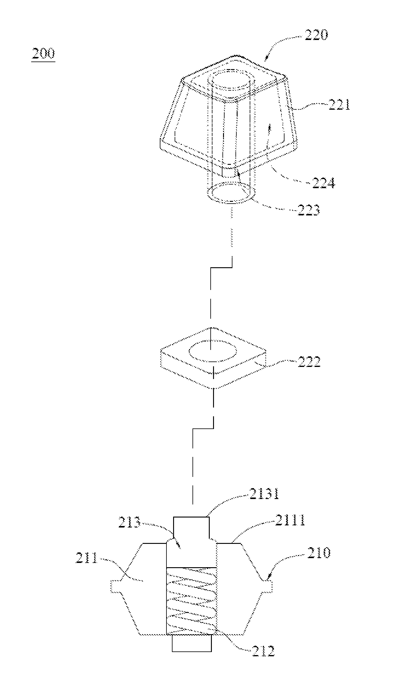
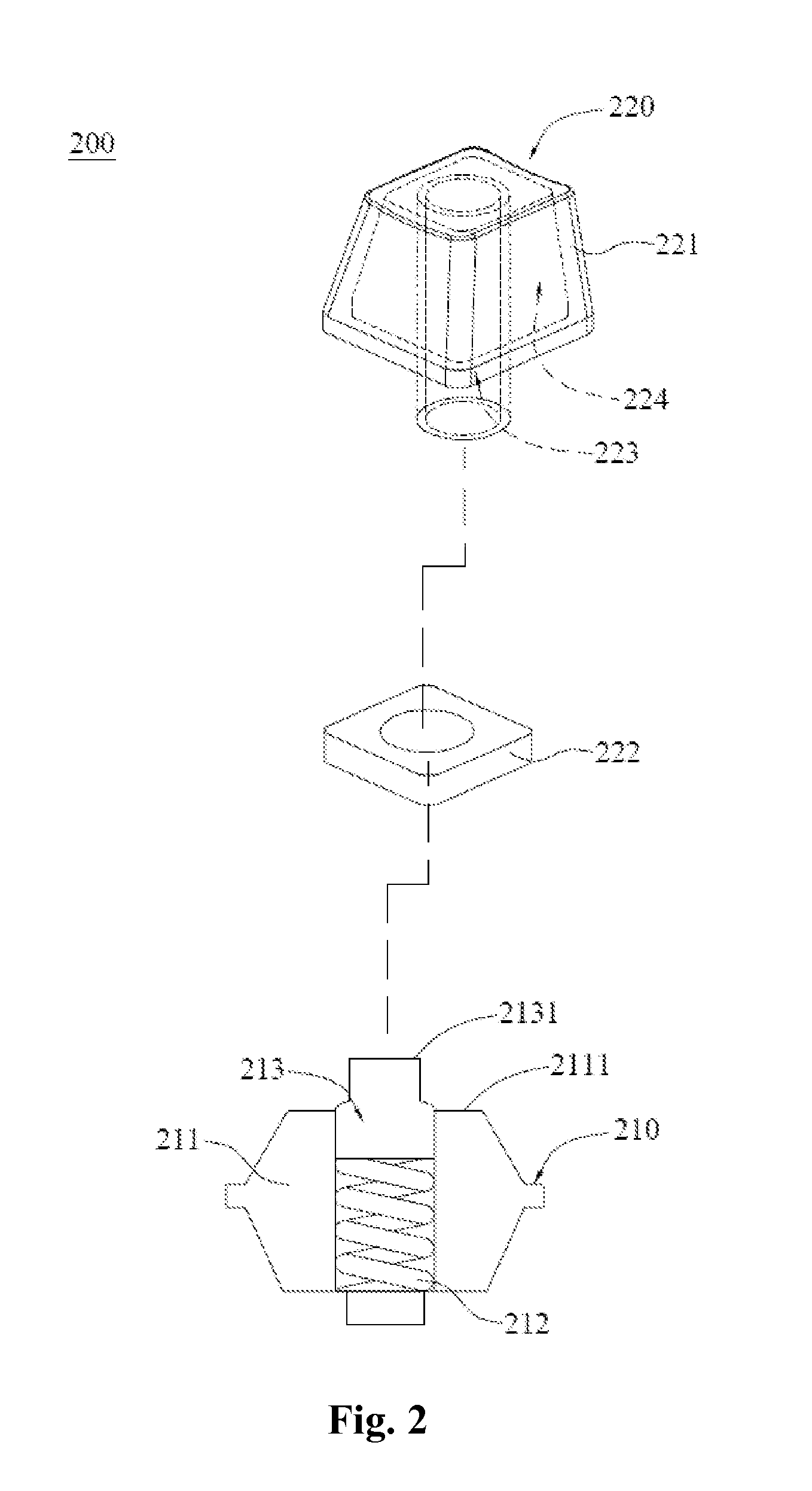
[0030]The key cap 220, in accordance with the second embodiment, includes a main body 221 and a cushion member 222. The main body 221 is made of thermoplastic materials such as polybutylece terephthalate (PBT) or polyformaldehyde (POM). Thermoplastic materials are easy to shape and have good crashworthiness and wear-resisting properties.

[0031]A top surface and a bottom surface opposite to the top surface are also defined in the main body 221. A coupling slot 223 and a trench 224 are formed at the bottom surface of the main body 221. More specifically, the coupling slot 223 is a blind hole formed at an inner portion of a protruding part extended from the bottom surface. The shape of the coupling slot 223 matches with the shape of the protruding member 2131 of the shaft 213. The trench 224 is a concave structure formed around the outer portion of the protruding part extended from the bottom surface.

[0032]The difference between the second embodiment and the first embodiment is that the...


PUM


Abstract

A keyboard includes a main board and at least one key structure positioned on the main board. The key structure includes a key switch and a key cap. The key cap is combined with the key switch. The key switch includes a key base and a shaft movably positioned on the key base. The keycap includes a main body and a cushion member. The main body is positioned on the shaft of the key switch. The main body is spaced apart from the contact surface of the key base. The main body is moved forward and backward relative to the key base with movement of the shaft. The cushion member is positioned at one side of the main body facing the contact surface. While the main body is moved to the contact surface, the cushion member abuts on the contact surface, so as to avoid the main body from hitting the key base directly, and hence minimizing the noise that is produced by the moving parts.

Description

BACKGROUND OF THE INVENTION[0001]1. Field of the Invention[0002]This disclosure relates to a key cap, key structure and a keyboard and, more particularly, to a key cap, a key structure with key in mechanistic model, and a keyboard with the key structures.[0003]2. Related Art[0004]Keyboards have become the dominant peripheral device for inputting words, symbols and numbers. In addition to computers, consumer electronics or large factory machines are also equipped with key structures that allow for input in order to operate these machines.[0005]Overtime keyboards have evolved in their designs and functions. For example, there are foldable keyboards, thin film keyboards, waterproof keyboards and keyboards with backlight. More common keyboards are divided into two types: mechanistic model and the thin film model.[0006]The structure of keys in mechanistic model includes (1) key cap, (2) key base, and (3) a shaft. The structure also includes other equipment located inside the key base suc...

Claims


Application Information

Patent Timeline
Patent Type & Authority Applications(United States)
IPC IPC(8): H01H13/84H01H13/02
CPCH01H13/02H01H13/84G06F3/02G06F3/0202H01H2221/044H01H2221/08H01H2221/084H01H2233/108H01H2235/03
Inventor LIN, YIN-YULAI, YEN-BOLIN, PEI-CHENCHEN, SHU I
Owner GIGA BYTE TECH CO LTD
Why Eureka
Try Eureka