Low solar transmittance coatings

a technology of low solar radiation and coating, applied in the direction of coatings, instruments, transportation and packaging, etc., can solve the problems of reducing the visible light transmission of the coating, negatively affecting the color of the coating, and reducing the durability of the coating, so as to achieve the effect of low solar radiation transmission and low solar radiation transmission

Active Publication Date: 2015-01-01
CARDINAL CG
View PDF12 Cites 8 Cited by
  • Summary
  • Abstract
  • Description
  • Claims
  • Application Information

AI Technical Summary

Benefits of technology

[0010]In certain embodiments, the invention provides a laminated glass assembly including two panes and an interlayer. One of the panes has a major surface bearing a low solar transmittance coating. The low solar transmittance coating comprises a first infrared-reflection film region, a second infrared-reflection film region, and a third infrared-reflection film region. The coating comprises, in sequence moving away from the noted major surface: a) a first transparent dielectric film region having an optical thickness, b) the first infrared-reflection film region, c) a second transparent dielectric film region having an optical thickness, d) the second infrared-reflection film region, e) a third transparent dielectric film region having an optical thickness, f) the third infrared-reflection film region, and g) a fourth transparent dielectric film region having an optical thickness. (The coating might optionally further include thin transitional layers separating the infrared-reflection film regions from the transparent dielectric film regions. Such transitional regions might transition from being more metallic adjacent to the IR film to having more dielectric properties further away from the IR film) In the present embodiments, the three infrared-reflection film regions have thicknesses that provide the laminated glass assembly with a solar transmittance of less than 0.34 and yet the laminated glass assembly has a visible transmittance of greater than 0.705. Preferably, the three infrared-reflection film regions have a combined thickness of greater than 300 Å and yet the laminated glass assembly exhibits a Delta Tvis, lami of less than about 4%. Further, in the present embodiments, the combined thickness of the three infrared-reflection film regions is greater than 300 Å in combination with the third infrared-reflection film region being thinner than the second infrared-reflection film

Problems solved by technology

However, this can also reduce the visible light transmission of the coating, and/or negatively impact the color of the coating, and/or decrease the durability of the coating.
Perhaps for thes

Method used


Image

  • Low solar transmittance coatings
  • Low solar transmittance coatings
  • Low solar transmittance coatings

Examples


Embodiment Construction

[0013]The following detailed description is to be read with reference to the drawings, in which like elements in different drawings have like reference numerals. The drawings, which are not necessarily to scale, depict selected embodiments and are not intended to limit the scope of the invention. Skilled artisans will recognize that the examples provided herein have many useful alternatives that fall within the scope of the invention.

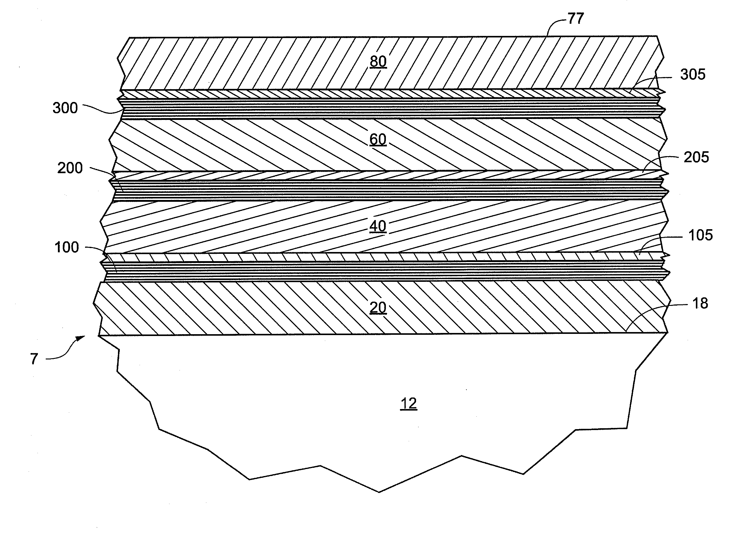
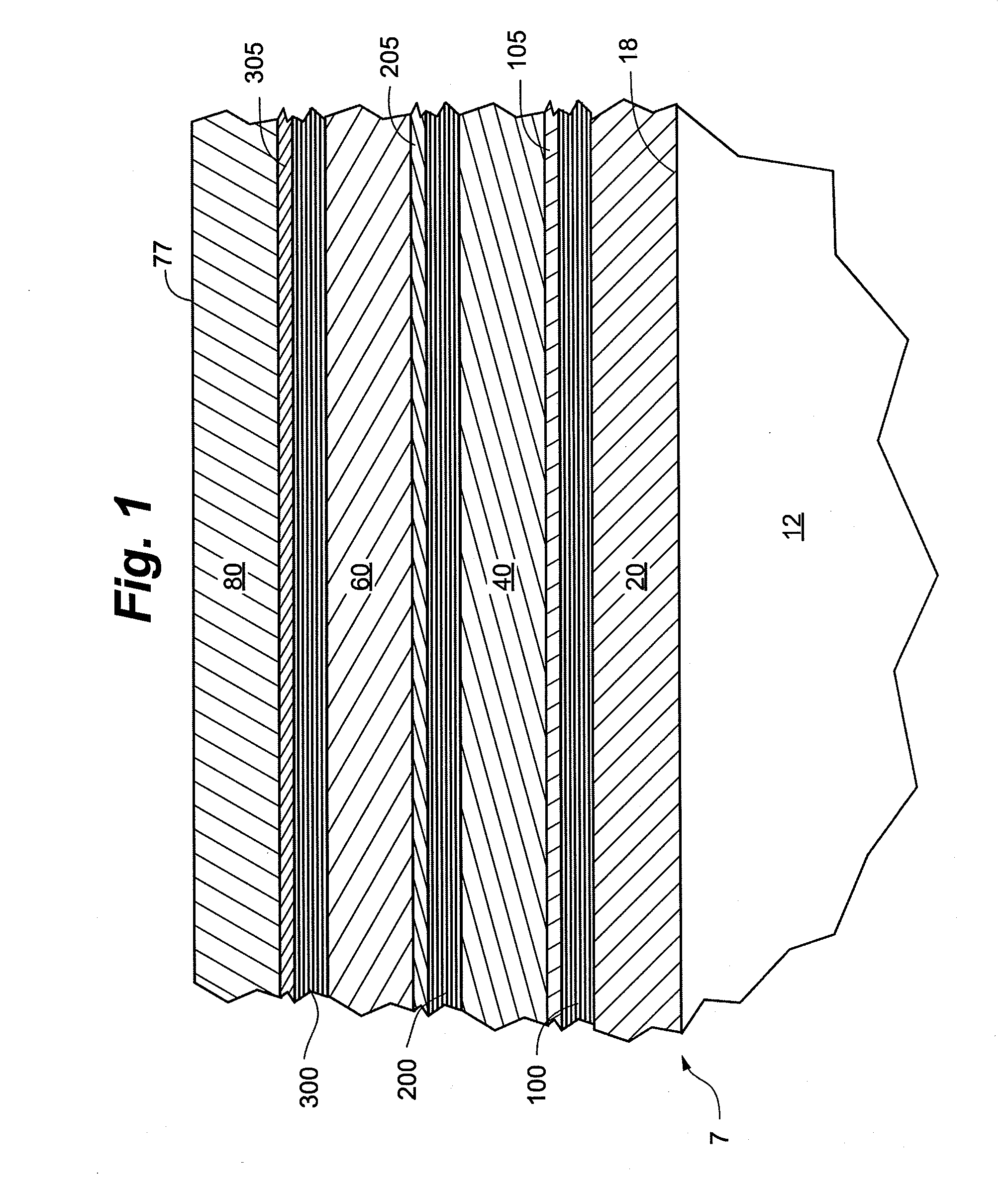
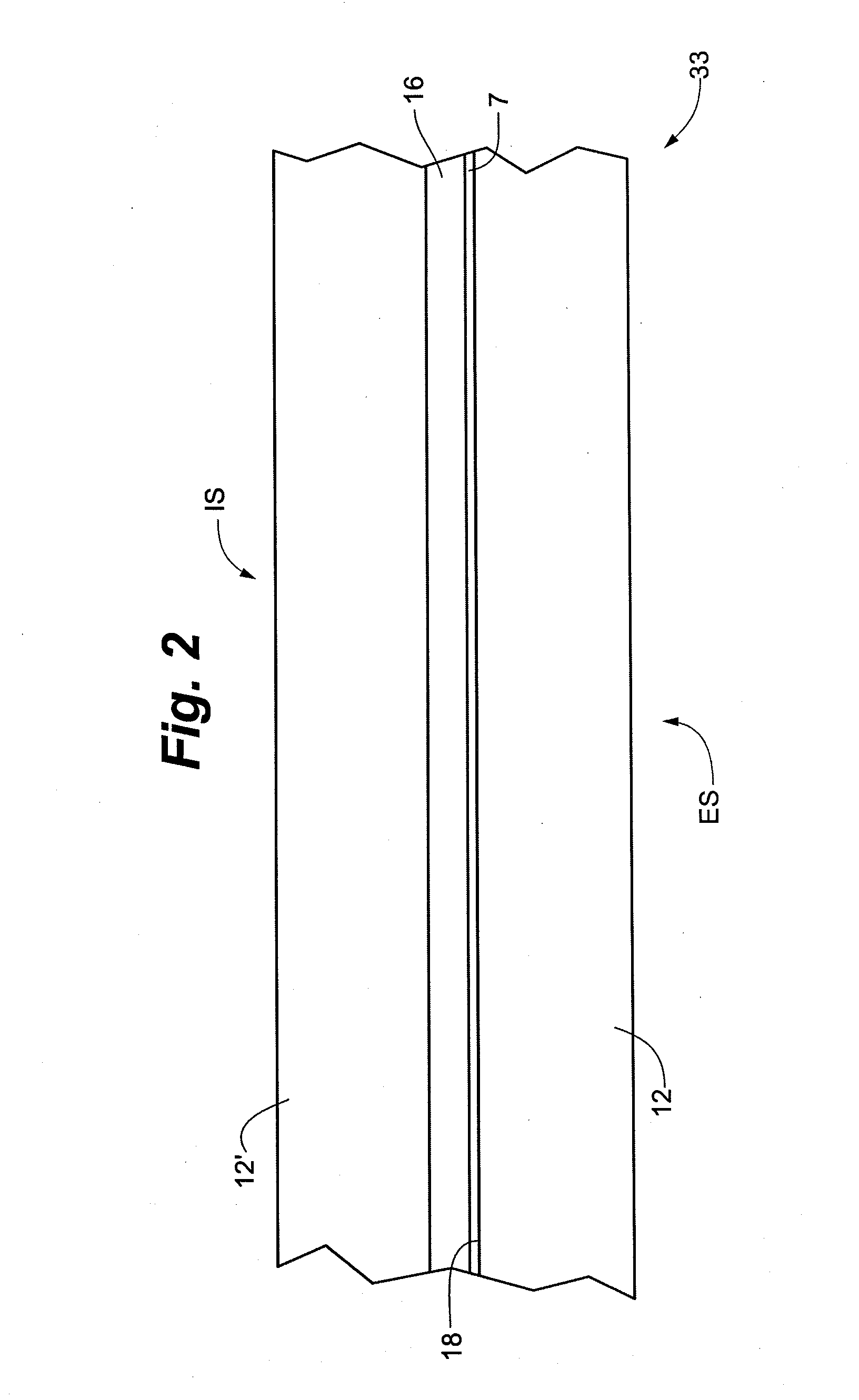
[0014]The present low solar transmittance coating 7 has a number of beneficial properties. The ensuing discussion reports some of these properties. In some cases, properties are reported for a single (e.g., monolithic) pane 12 bearing the present coating 7 on one surface 18. In other cases, properties are reported for a laminated glass assembly 33 wherein two panes 12, 12′ are laminated together with an interlayer 16, and where the present coating 7 is on the interior surface 18 of the outboard pane 12. In such cases, the reported properties reflect use...


PUM

PropertyMeasurementUnit
Temperatureaaaaaaaaaa

Abstract

The invention provides low solar transmittance coatings that have particularly low solar transmittance. The coating includes three infrared-reflection film regions, which may each comprise silver. In some cases, the coating is incorporated into a laminated glass assembly.

Description

FIELD OF THE INVENTION[0001]The present invention relates to thin film coatings for glass and other substrates. In particular, this invention relates to low solar transmittance coatings. Also provided are methods and equipment for depositing such coatings, as well as laminated glass assemblies incorporating such a coating.BACKGROUND OF THE INVENTION[0002]Low solar transmittance coatings are well known in the art. Typically, they include one or two layers of infrared-reflective film and two or more layers of transparent dielectric film. The infrared-reflective film, which will commonly be a conductive metal like silver, gold, or copper, reduces the transmission of heat and light through the coating. The dielectric film is used to antireflect the infrared-reflective film for part of the visible light, and to control other properties and characteristics of the coating, such as color and durability. Commonly used dielectric materials include oxides of zinc, tin, indium, bismuth, and tit...

Claims


Application Information

Patent Timeline
IPC IPC(8): C03C23/00C03C17/36B32B37/24B32B38/18B32B17/10B32B37/06G02B1/11B32B37/10
CPCC03C17/366G02B1/11B32B17/10201B32B17/10229B32B17/10036C03C17/3681B32B2309/022B32B37/10B32B38/1866B32B37/24C03C23/007B32B2037/243B32B2311/08B32B37/06B32B17/10761C03C17/36C03C17/3626C03C17/3639C03C17/3644C03C17/3652Y10T428/24628Y10T428/2495Y10T428/24975
Inventor EBY, ERIC H.HARTIG, KLAUS H.W.
Owner CARDINAL CG
Why Eureka
Try Eureka