High intensity focused ultrasound enhanced by cavitation

a high-intensity, focused ultrasound technology, applied in the field of high-intensity focused ultrasound, can solve the problems of increasing local heating and other problems, and achieve the effects of reducing heating, increasing heating, and reducing ultrasound

Inactive Publication Date: 2015-01-01
KONINKLJIJKE PHILIPS NV
View PDF7 Cites 12 Cited by
  • Summary
  • Abstract
  • Description
  • Claims
  • Application Information

AI Technical Summary

Benefits of technology

[0009]Usually in HIFU therapies the target is to cause ablations of tissues purely based on thermal mechanisms, but when intensities are high enough also other phenomena, such as cavitation, may appear. Cavitation or other bubble activity deteriorate the predictability of thermal ablations and is therefore to be minimized. However, bubbles may also increase the local heating and thus improve the therapy efficiency.
[0044]In another embodiment ultrasonic cavitations at multiple cavitation locations form an acoustic barrier. The bubbles generated by the ultrasonic cavitations make it difficult for ultrasound to pass the region with the bubbles. In this way forming cavitations at the multiple cavitation locations may form an acoustic barrier which blocks or partially blocks ultrasound from traveling through it.

Problems solved by technology

Also, he combined interactions of bubbles with the short pulse and the longer sonication may generate an acoustic barrier in the focus that prevents acoustic propagation beyond the focus which also may cause increased local heating.

Method used


Image

  • High intensity focused ultrasound enhanced by cavitation
  • High intensity focused ultrasound enhanced by cavitation
  • High intensity focused ultrasound enhanced by cavitation

Examples


Embodiment Construction

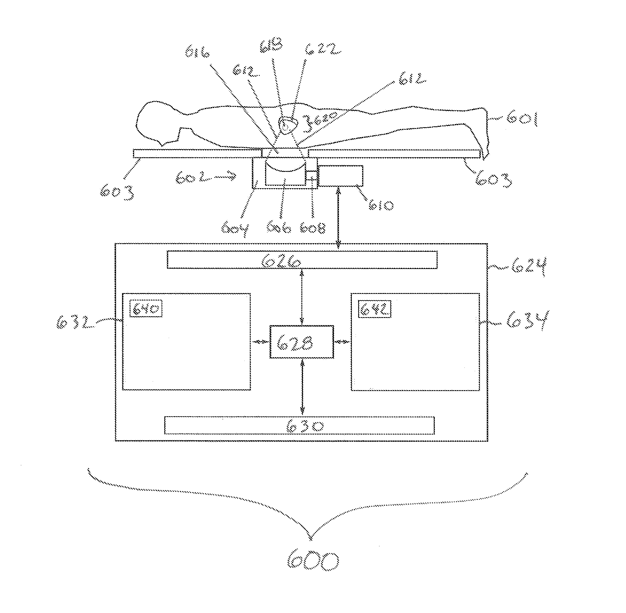
[0060]Like numbered elements in these figures are either equivalent elements or perform the same function. Elements which have been discussed previously will not necessarily be discussed in later figures if the function is equivalent.

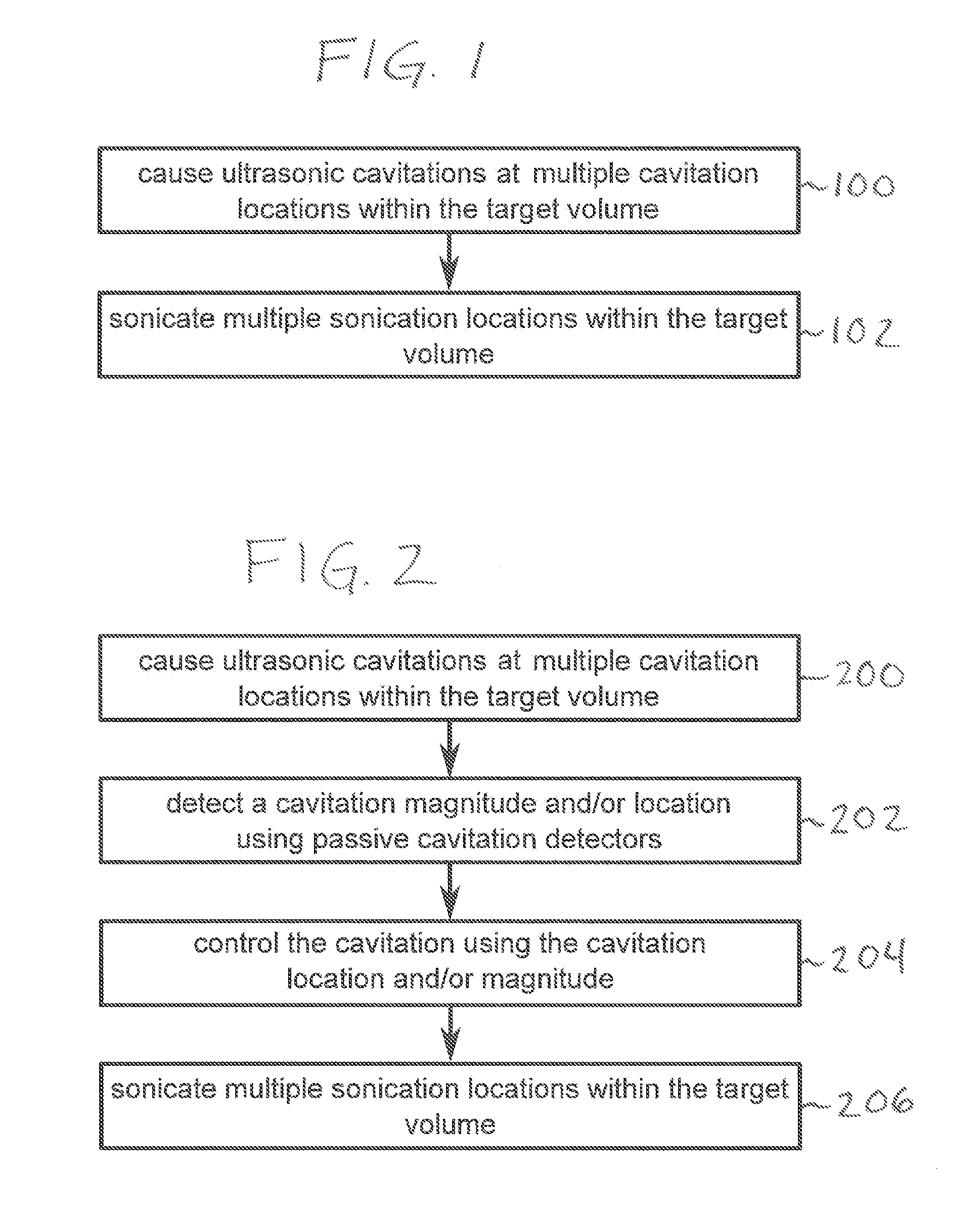
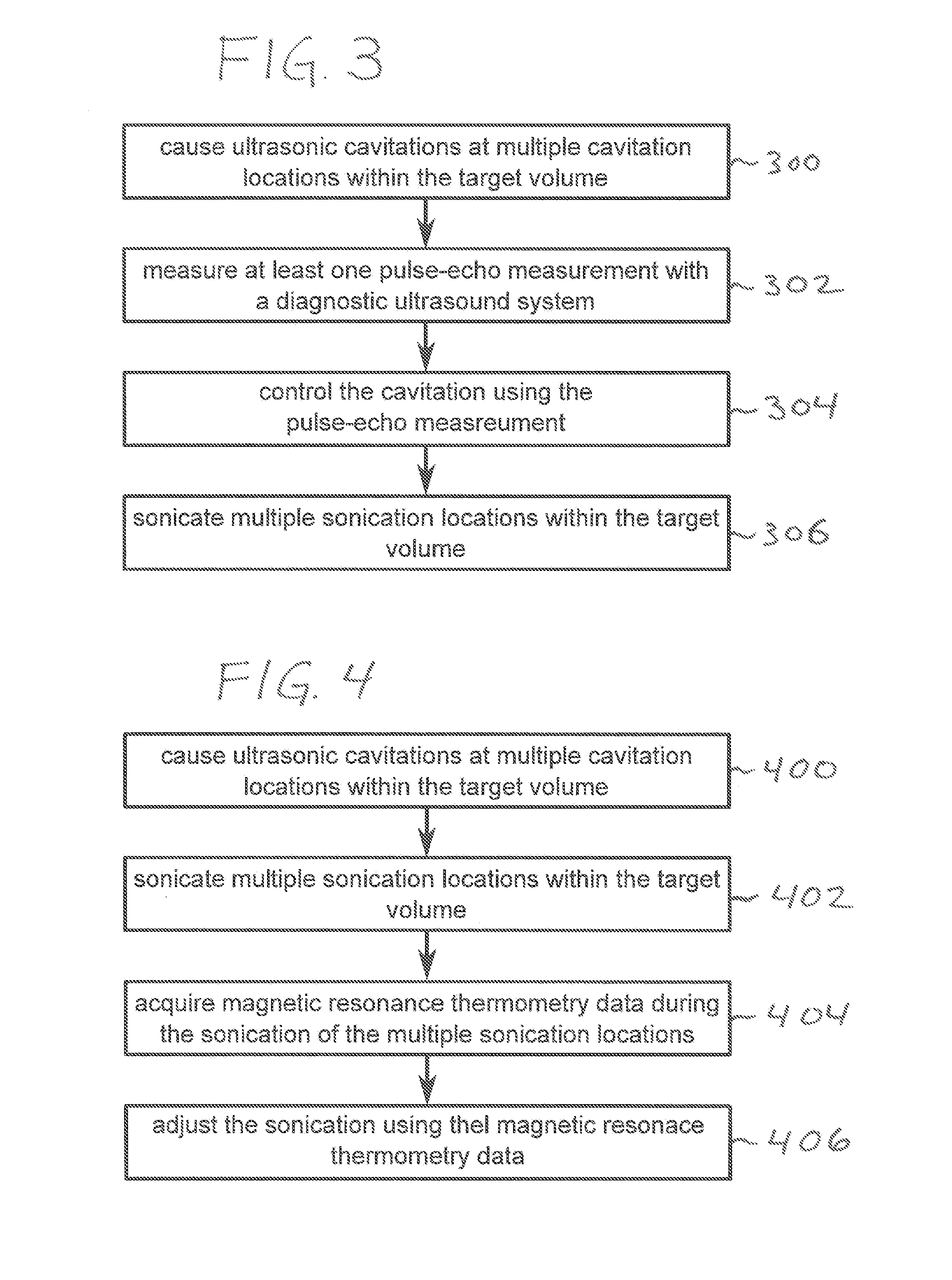
[0061]FIG. 1 shows a flow diagram which illustrates a method according to an embodiment of the invention. First in step 100 ultrasonic cavitations at multiple cavitation locations are caused within a target volume using a high-intensity focused ultrasound system. Next in step 102 multiple sonication locations are sonicated within the target volume.

[0062]FIG. 2 shows a flow diagram which illustrates a method according to a further embodiment of the invention. First in step 200 ultrasonic cavitations are caused at multiple cavitation locations within the target volume. Next at step 202 a cavitation spectrum and / or cavitation location are detected using passive cavitation detector or detectors. Detecting the magnitude will give information about the streng...


PUM


Abstract

A medical apparatus (600, 700, 800, 900) comprising a high intensity focused ultrasound system (602) configured for generating focused ultrasonic energy (612) for sonicating within a target volume (620) of a subject (601). The high intensity focused ultrasound comprises an ultrasonic transducer (606) with a controllable focus (618). The apparatus further comprises a memory (634) containing machine executable for controlling the medical apparatus and a processor (628) for executing the instructions. Execution of the instructions causes the processor to cause (100, 200, 300, 400, 502) ultrasonic cavitations at multiple cavitation locations (622, 1002) within the target volume using the high intensity focused ultrasound system. Execution of the instructions further cause the processor to sonicate (102, 206, 306, 402, 504) multiple sonication locations (1004) within the target volume using the high intensity focused ultrasound system. The multiple sonication locations and the multiple cavitation locations are targeted by adjusting the controllable focus.

Description

TECHNICAL FIELD[0001]The invention relates to high intensity focused ultrasound, in particular to cavitation enhanced sonication of a target volume.BACKGROUND OF THE INVENTION[0002]High-intensity focused ultrasound (HIFU) may be used to perform non-invasive thermal ablations. Conventional HIFU therapies rely on classical absorption of ultrasound energy through viscosity and heat conductivity losses that induce temperature increase in tissues. Usually the thermal ablations offer a good predictability both in temperature increase and ablated area. In volumetric HIFU therapy the focal point is steered electronically along concentric circles in the targeted area in order to achieve a controlled temperature increase on a larger area and hence, a larger ablated area.[0003]If the target area is deep seated or for example well perfused, the applied energy needs to be increased either by increasing the acoustic intensity or the duration of the sonication. However, this increases also the the...

Claims


Application Information

Patent Timeline
Patent Type & Authority Applications(United States)
IPC IPC(8): A61B18/04
CPCA61B18/04A61B2018/00982A61B2018/00648A61B2018/00577A61N7/02A61N2007/0091A61B2019/5236A61B2017/00084G01R33/4804G01R33/4814A61B5/055A61B17/2256A61N2007/0078A61N2007/0065A61N2007/0095A61B2090/374F04C2270/041
Inventor TILLANDER, MATTI OSKARIKOHLER, MAX OSKARSOKKA, SHUNMUGAVELU
Owner KONINKLJIJKE PHILIPS NV
Why Eureka
Try Eureka