
Press machine

Active Publication Date: 2015-01-08
AIDA ENG LTD
View PDF7 Cites 3 Cited by
  • Summary
  • Abstract
  • Description
  • Claims
  • Application Information

AI Technical Summary

Benefits of technology

The present invention provides a press machine that can make high-quality products without sudden and excessive movement of the actuator. This is possible by preventing the abrupt and excessive rise of the actual bottom dead center position that occurs with the raising and lowering of the actuator. This allows for sufficient crimping and avoids instability in the bottom dead center position. The machine can also maintain a stable bottom dead center position even without a stopper block. In some embodiments, the machine can achieve a higher control response speed, resulting in a higher-quality product.

Problems solved by technology

Specifically, when the actuator is depressurized and lowered or pressurized and raised during the correction control for the bottom dead center position, an abrupt and excessive change occurs in the bottom dead center position of the slide.
Even when the bottom dead center is monitored in every shot, due to the feedback control, it is impossible to prevent the abrupt and excessive change of the bottom dead center position that is caused by the disturbance such as the raising and lowering operation of the actuator.
In other words, irrespective of whether the press operation is performed at changing speed or constant speed, the bottom dead center position that is abruptly changed due to the disturbance inevitably results in the actual bottom dead center position deviating from the target bottom dead center position.
The operation is brought into an oscillatory state due to the abrupt and excessive change of the bottom dead center position that occurs unexpectedly.
That is, the operation is brought into an uncontrollable state, which increases a risk in that the bottom dead center position fluctuates in a severely undulating manner.
Even during the correction control for the bottom dead center position, however, the actual bottom dead center position is raised in an abrupt and excessive manner (“Dyu” of FIGS. 9A and 9B) due to the raising operation of the actuator.
As a result, the fitting and crimping pressure decreases, and hence the crimping is insufficient, which causes such an adverse effect that the thin plates are separated from each other.
This adverse effect is caused from the fact that, in the case of the raising operation, the mechanical restricting unit such as the stopper block cannot be provided unlike the case of the lowering operation.
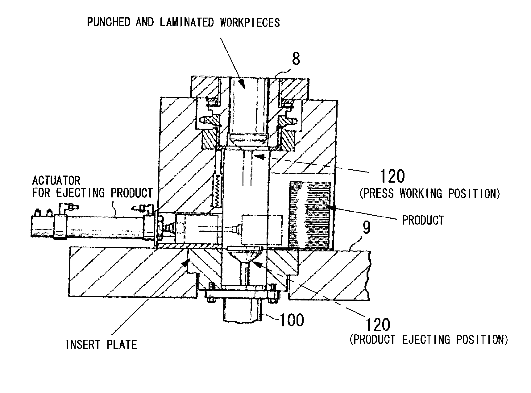
Further, when the bottom dead center position fluctuates significantly toward the lower side due to the oscillation (FIG. 10), the depth of the projections and depressions becomes larger than originally intended, and hence the projecting portions are disengaged due to crimping failure.
In addition, when the stopper block is provided in the die, the amount of abutment of the slide against the stopper block increases considerably, and hence the slide bounces significantly.
As a result, the precision of the product is deteriorated and the life of the die is reduced.
Eventually, the risk of an overload on the press machine increases.
Further, even in the bottom dead center position correcting device (Japanese Patent Application Laid-open No. 2009-274080), the abrupt and excessive change of the bottom dead center of the slide has not been taken into consideration.

Method used


Image

  • Press machine
  • Press machine
  • Press machine

Examples


Embodiment Construction

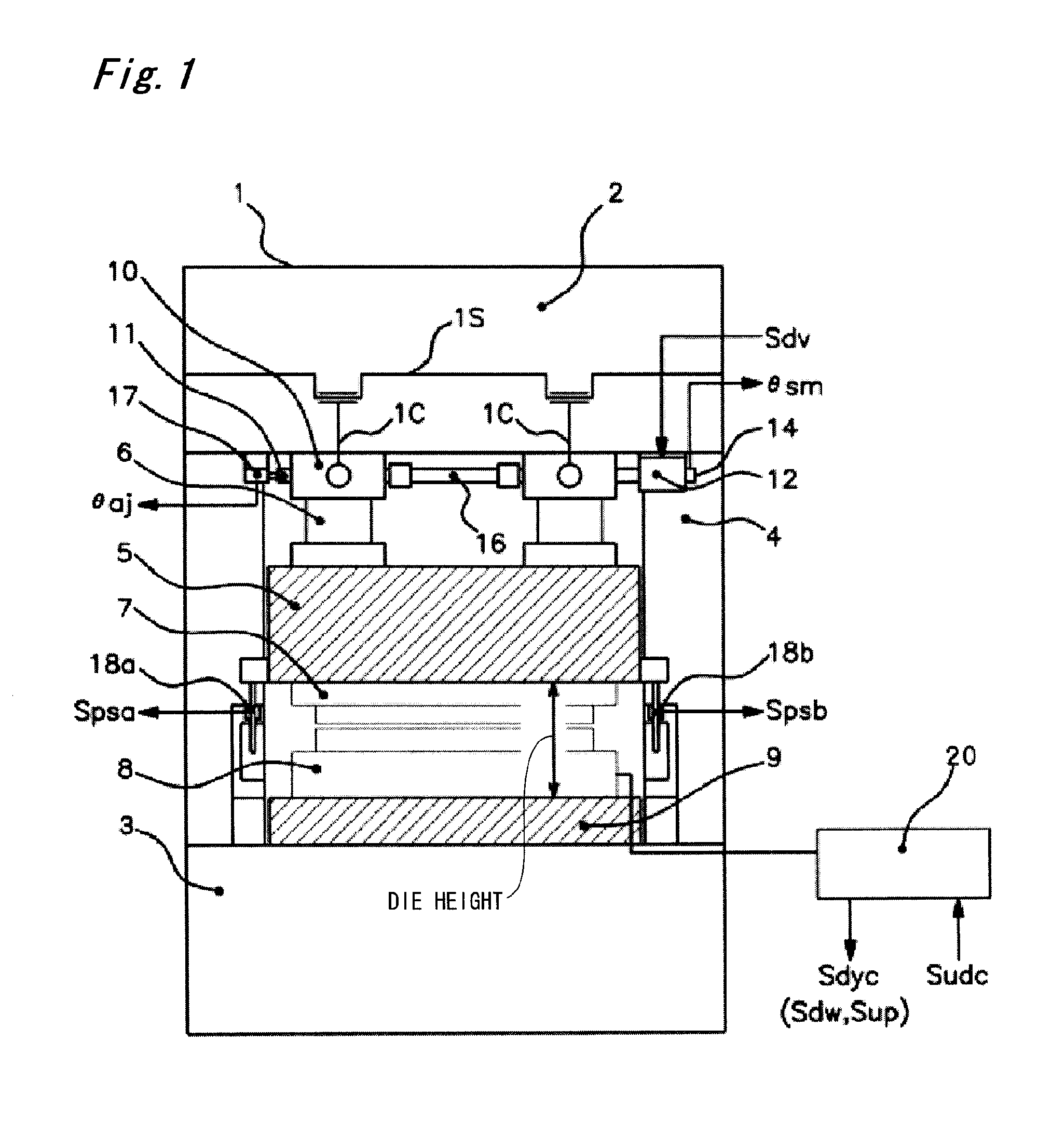
[0074]In the following, an exemplary embodiment of the present invention is described in detail with reference to the accompanying drawings (FIGS. 1 to 6).

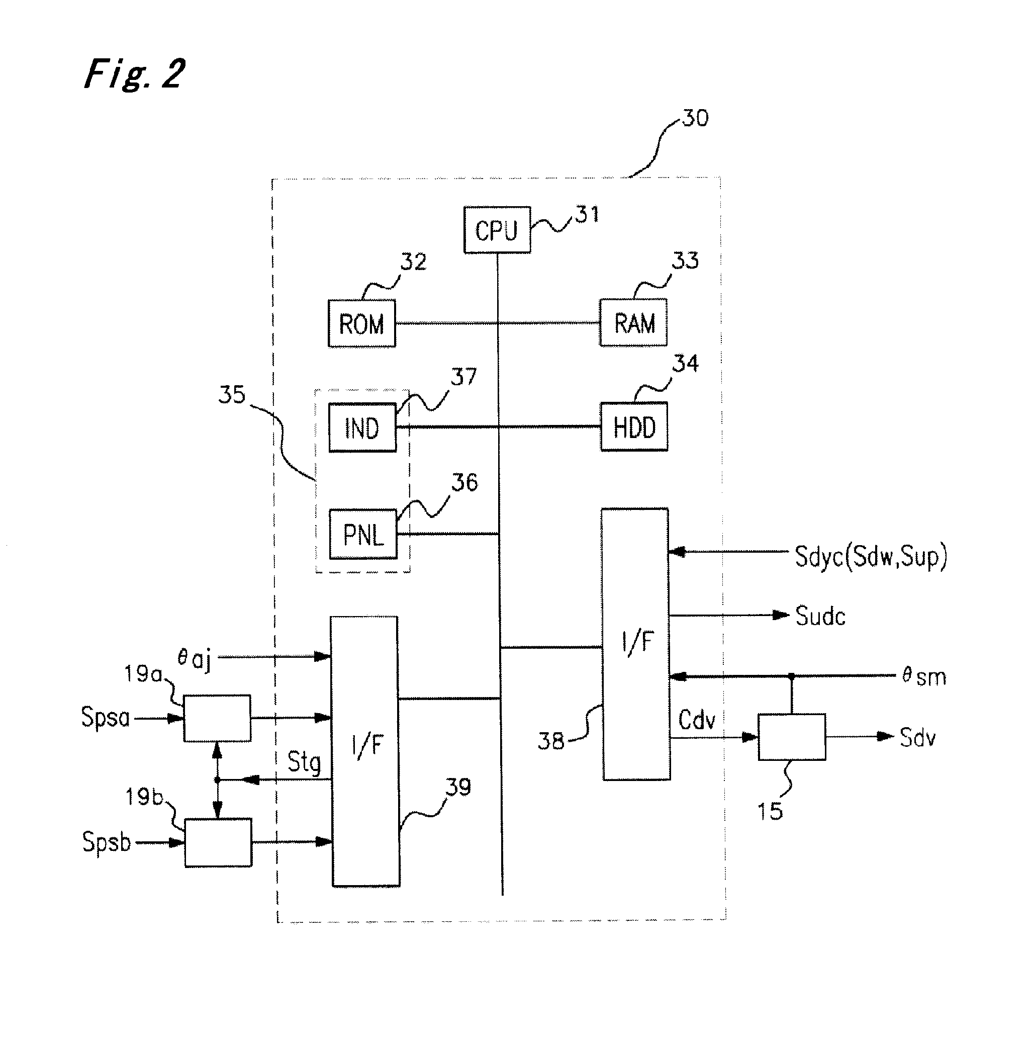
[0075]The present invention provides a press machine, including: a bottom dead center position correction control section (31, 33, 34), which performs, based on a preset target bottom dead center position Hx and a detected bottom dead center position (Spsa, Spsb) obtained during a press operation, positional correction so that an actual bottom dead center position of a slide 5 is adjusted to the target bottom dead center position Hx; a selected bottom dead center position setting section (35 and 31, 33, 34), which sets a selected bottom dead center position; and a bottom dead center position switching section (31, 33, 34), which switches the target bottom dead center position to the selected bottom dead center position. The bottom dead center position correction control section (31, 33, 34) is configured to perform, based on the s...


PUM

PropertyMeasurementUnit
Distanceaaaaaaaaaa

Abstract

A press machine is provided with a bottom dead center position correction control section, a selected lower bottom dead center position setting section, and a bottom dead center position switching section. The bottom dead center position correction control section is configured to perform, based on the selected bottom dead center position after the switching and the detected bottom dead center position, positional correction so that the actual bottom dead center position of the slide is adjusted to the selected bottom dead center position.

Description

FIELD OF THE INVENTION[0001]The present invention relates to a press machine including an actuator capable of lowering a workpiece support unit from a press working position by a distance corresponding to a predetermined amount or more, and raising the workpiece support unit so as to be returned to the press working position after ejecting a workpiece.BACKGROUND[0002]Press machines are configured to manufacture a product by press working to be performed in cooperation between an upper die and a lower die while raising and lowering a slide. One important factor to determine the precision of the product is that a bottom dead center position of the slide is maintained to be constant.[0003]In general, the bottom dead center position and a press speed have such a close relationship as illustrated in FIG. 11. In FIG. 11, the horizontal axis represents the number of shots of the press machine, and the vertical axis represents the bottom dead center position of the slide and the press speed...

Claims


Application Information

Patent Timeline
IPC IPC(8): B30B15/00
CPCB30B15/0041B21D28/22B21D45/003B30B15/14B30B15/26H02K15/022
Inventor YAMANOUCHI, AKIRA
Owner AIDA ENG LTD
Learn More