Thin membrane marking system and controlling method thereof

A marking system and thin-film technology, which is applied in the fields of electrography, manufacturing tools, and electrical recording technology using charge patterns, etc., can solve problems such as productivity problems and parts ID code forgery

Inactive Publication Date: 2003-11-19
TECHNICS
View PDF0 Cites 2 Cited by
  • Summary
  • Abstract
  • Description
  • Claims
  • Application Information

AI Technical Summary

Problems solved by technology

[0003] However, the typical method of engraving a part identification (ID) code on a metal panel and attaching it to a mechanical part with screws or by welding exists due to indispensable fixing devices such as metal panels, screws, or welding tools. cost problem
Also, because of the extra work required to fasten the metal panels to the mechanical parts, there are produ

Method used


Image

  • Thin membrane marking system and controlling method thereof
  • Thin membrane marking system and controlling method thereof
  • Thin membrane marking system and controlling method thereof

Examples


Embodiment Construction

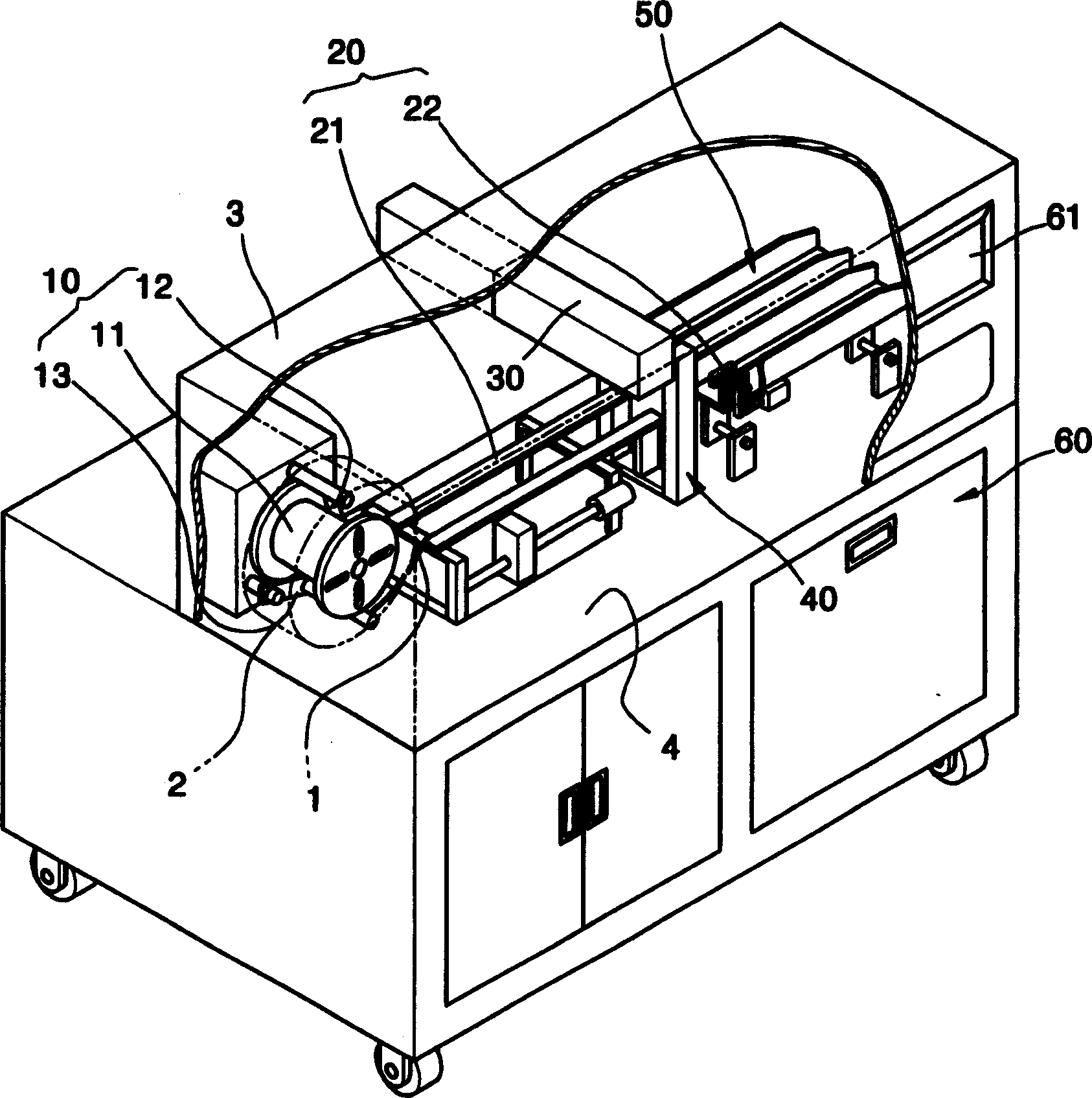
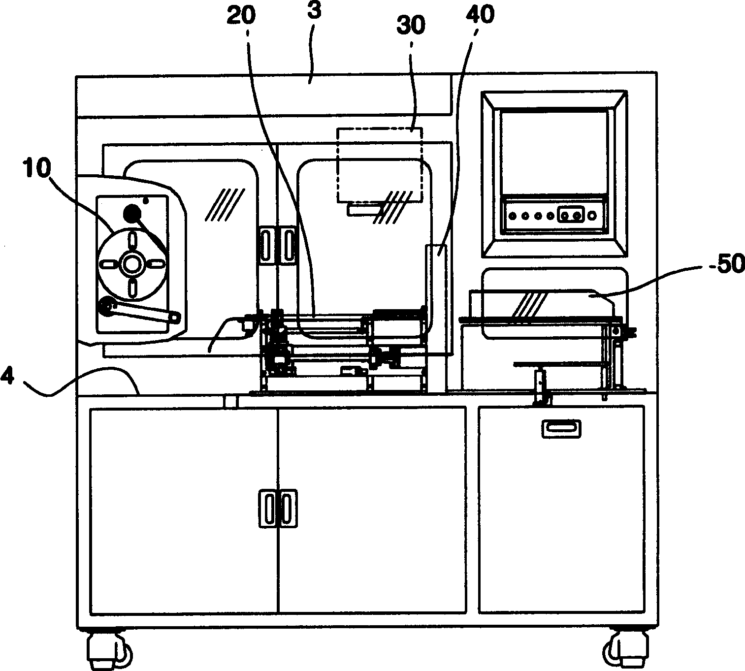
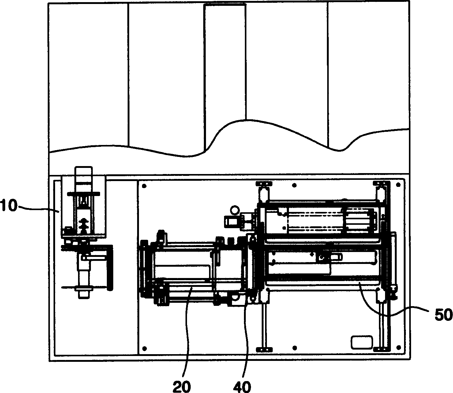
[0040] refer to Figures 1 to 4, shows a film marking system according to a preferred embodiment of the present invention, which uses a laser to mark various characters, numbers or other codes on the adhesive photosensitive film 2 . The film marking system includes: a box body 3, which forms the appearance of the system and protects various units of the system from external substances; a table body 4, which is formed inside the box body 3, and has a predetermined height Loading unit 10; Transport unit 20; Laser module 30; Cutting unit 40; Stacking unit 50; body 4.

[0041] The loading unit 10 is a device for loading and unwinding the film roll 2 to continuously supply the film 1 wound on the film roll 2 to form a roll. refer to Figures 5 to 8 , the loading unit 10 includes: a reel 11 , a material induction plate 12 and a film tension regulator 13 .

[0042] The reel 11 is engaged with the center of the film roll 2 for loading and supporting the film roll 2 which is rotate...


PUM


Abstract

The invention discloses film marker system that enables continuous mass-production by automating the manufacturing process and to provide the method of controlling the same. This film marker system comprises a loading device for supplying a film, a conveying device for conveying the supplied film to an irradiation position, a laser module for marking a desired character, numeral or symbol by irradiating a laser light to the film provided on the irradiation position, a cutting device for cutting the marked film in a predetermined length, a piling device for sequentially piling up the cut films on a detachable jig, and a control section for controlling the operations of the above devices and the laser module by applying the control signals thereto.

Description

technical field [0001] The invention relates to a film marking system and a control method thereof. In particular, the present invention relates to a thin film marking system allowing mass production through an automated manufacturing process, and a method of controlling a thin film marking system. Background technique [0002] In order to facilitate the identification of mechanical parts, information on various mechanical parts of motor vehicles, heavy equipment, factory equipment, engines, etc. is represented as relating to serial numbers, manufacturers, model names, manufacturing codes or dates, operating manuals or operating warnings, etc. Alpha (alpha) digital codes, and use special ink or paint, or use permanent marking techniques such as steel metal processing to engrave such alpha (alpha) digital codes on metal panels such as aluminum panels, and then use screws, rivets , adhesives, or attach engraved metal panels to mechanical parts by welding. [0003] However, t...

Claims


Application Information

Patent Timeline
IPC IPC(8): B41J2/44B23K26/00B23K101/16B41J2/00B41J2/455B41J2/47G03G15/04G09F3/00G09F3/03
CPCB41J2/442B41J2/455B41J2/485
Inventor 边英植金泰政
Owner TECHNICS
Why Eureka
Try Eureka