Motor and method of manufacturing motor

a manufacturing method and motor technology, applied in the direction of windings, winding insulation materials, cooling/ventilation arrangements, etc., can solve the problems of difficult to further improve the heat dissipation efficiency of the motor, the gap between the tooth is large, and the motor may easily become overheated, so as to promote the dissipation of heat out of the motor

Active Publication Date: 2015-01-08
NIDEC CORP
View PDF14 Cites 24 Cited by
  • Summary
  • Abstract
  • Description
  • Claims
  • Application Information

AI Technical Summary

Benefits of technology

[0011]According to the above-described preferred embodiment of the present invention, heat generated in each coil is allowed to be transferred to the tooth through the resin body. In particular, the inner resin portion is arranged between the tooth and the coil and between the tooth and the insulator. In addition, the coil is arranged to be in contact with the outer resin portion as well. Thus, a large area of a path along which the heat is transferred from the coil to the tooth is secured. Dissipation of heat out of the motor is thus promoted. Moreover, the inner and outer resin portions are arranged to be continuous with each other through the connecting resin portion. This makes it easy to mold the resin body.

Problems solved by technology

However, there are a great number of minute gaps between the tooth and the coil, and these gaps constitute a factor in preventing the heat from being effectively transferred from the coil to the tooth.
When transmission of the heat from the coil is insufficient, the motor may easily become overheated.
Therefore, according to a structure of JP-A 2005-012861, there are only a limited number of paths along which the heat is transferred from the coil to the tooth, and it is thus difficult to further improve heat dissipation efficiency of the motor.

Method used


Image

  • Motor and method of manufacturing motor
  • Motor and method of manufacturing motor
  • Motor and method of manufacturing motor

Examples


first preferred embodiment

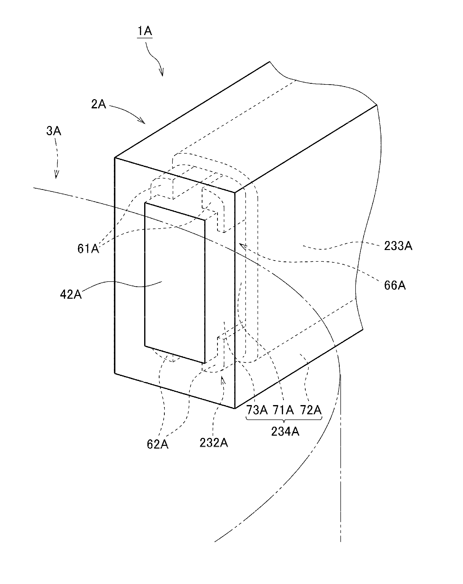
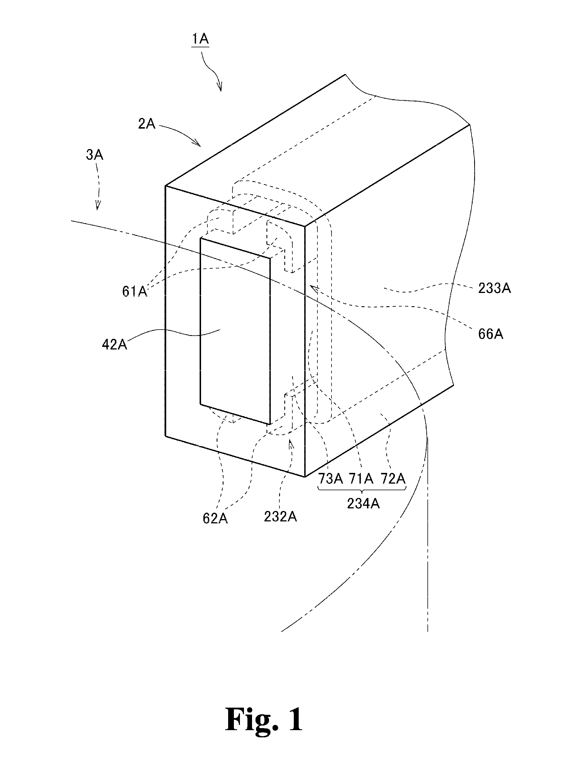
[0028]FIG. 1 is a partial perspective view of a portion of a motor 1A according to a preferred embodiment of the present invention. As illustrated in FIG. 1, the motor 1A includes a stationary portion 2A and a rotating portion 3A. The rotating portion 3A is supported to be rotatable about a central axis with respect to the stationary portion 2A.

[0029]The stationary portion 2A preferably includes a plurality of teeth 42A, insulators 232A, and coils 233A. Each of the teeth 42A is preferably arranged to have the shape of a column extending in a radial direction with respect to the central axis, and includes a pair of circumferential side surfaces extending in an axial direction. Each insulator 232A is arranged to cover portions of a surface of a separate one of the teeth 42A. Each coil 233A is defined by a conducting wire wound around a separate one of the insulators 232A. The rotating portion 3A is arranged radially inward of the teeth 42A, the insulators 232A, and the coils 233A.

[003...

second preferred embodiment

[0034]Next, a second preferred embodiment of the present invention will now be described below.

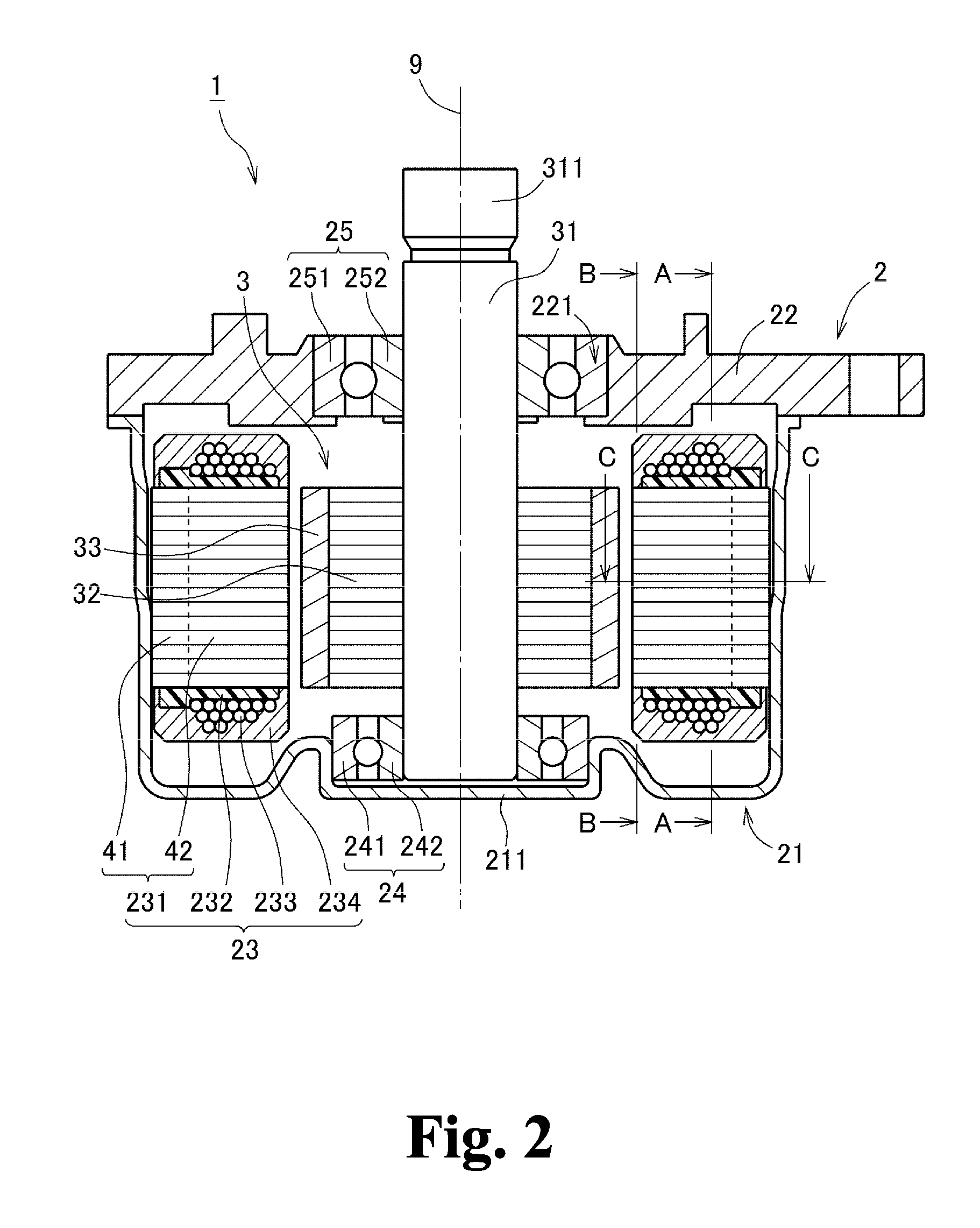
[0035]A motor 1 according to the present preferred embodiment is preferably, for example, installed in an automobile and used to generate a driving force for a steering system. Note, however, that motors according to other preferred embodiments of the present invention may be used for other known purposes, and are not limited to motors for power steering systems. For example, a motor according to a preferred embodiment of the present invention may be used as a driving source for another component of the automobile, e.g., a fan used for engine heat dissipation. Also, motors according to preferred embodiments of the present invention may be installed in household electrical appliances, office automation appliances, medical appliances, and so on, and used to generate a variety of driving forces.

[0036]FIG. 2 is a vertical cross-sectional view of the motor 1 according to the present preferred e...


PUM

PropertyMeasurementUnit
shapeaaaaaaaaaa
thermosettingaaaaaaaaaa
circumferential widthaaaaaaaaaa

Abstract

A stationary portion of a motor includes resin bodies including an inner and outer resin portion arranged between a tooth and a coil and between the tooth and an insulator. The outer resin portion covers circumferentially outer sides and axially outer sides of the coil. The inner and outer resin portions are continuous with each other through a connecting resin portion. The insulator includes an opening portion arranged to extend along circumferential side surfaces of the tooth. The inner resin portion is arranged to contact the circumferential side surfaces of the tooth and a conducting wire in the opening portion. Heat generated in the coil is transferred to the tooth through the resin body such that a large area of a path along which the heat is transferred from the coil to the tooth is secured.

Description

BACKGROUND OF THE INVENTION[0001]1. Field of the Invention[0002]The present invention relates to a motor and a method of manufacturing the motor.[0003]2. Description of the Related Art[0004]In a known motor, an insulator made of a resin is attached to each tooth of a stator and a conducting wire is wound around the insulator to define a coil. The insulator is arranged to intervene between the tooth and the coil to provide electrical insulation therebetween. A known motor including such an insulator is described, for example, in JP-A 2005-012861.[0005]During driving of the motor, heat is generated in each coil because of a drive current. It is desirable that the heat generated in the coil should be transmitted out of the motor through, for example, the insulator and the tooth. However, there are a great number of minute gaps between the tooth and the coil, and these gaps constitute a factor in preventing the heat from being effectively transferred from the coil to the tooth. When tra...

Claims


Application Information

Patent Timeline
Patent Type & Authority Applications(United States)
IPC IPC(8): H02K3/34H02K3/30H02K9/22H02K15/08
CPCH02K3/345H02K9/22H02K3/30H02K15/08H02K1/148H02K3/522H02K15/022Y10T29/49009H02K9/223H02K2213/12
Inventor UCHITANI, YOSHIHIROTANAKA, YUJIYOKOGAWA, TOMOYOSHI
Owner NIDEC CORP
Why Eureka
Try Eureka