Imaging lens and imaging apparatus equipped with the imaging lens

a technology of imaging lens and imaging apparatus, which is applied in the field of fixed focus imaging lens, can solve the problem of difficult application of this imaging lens to a compact imaging element capabl

Active Publication Date: 2015-01-08
JIANGXI OFILM OPTICAL CO LTD
View PDF1 Cites 108 Cited by
  • Summary
  • Abstract
  • Description
  • Claims
  • Application Information

AI Technical Summary

Benefits of technology

[0063]It is preferable for the focal length f2 of the second lens L2 and the focal length f of the entire system to satisfy Conditional Formula (2) below.
[0064]In addition, it is preferable for the focal length f1 of the first lens L1 and the focal length f of the entire system to satisfy Conditional Formula (3) below.
[0065]In addition, it is preferable for the focal length f3 of the third lens L3 and the focal length f of the entire system to satisfy Conditional Formula (4) below.
[0066]In addition, it is...

Problems solved by technology

The imaging lens disclosed in Japanese Unexamined Patent Publication No. 7 (1995)-281089 has a large F number, and it is difficult for thi...

Method used


Image

  • Imaging lens and imaging apparatus equipped with the imaging lens
  • Imaging lens and imaging apparatus equipped with the imaging lens
  • Imaging lens and imaging apparatus equipped with the imaging lens

Examples


Embodiment Construction

[0040]Hereinafter, embodiments of the present invention will be described in detail with reference to the attached drawings.

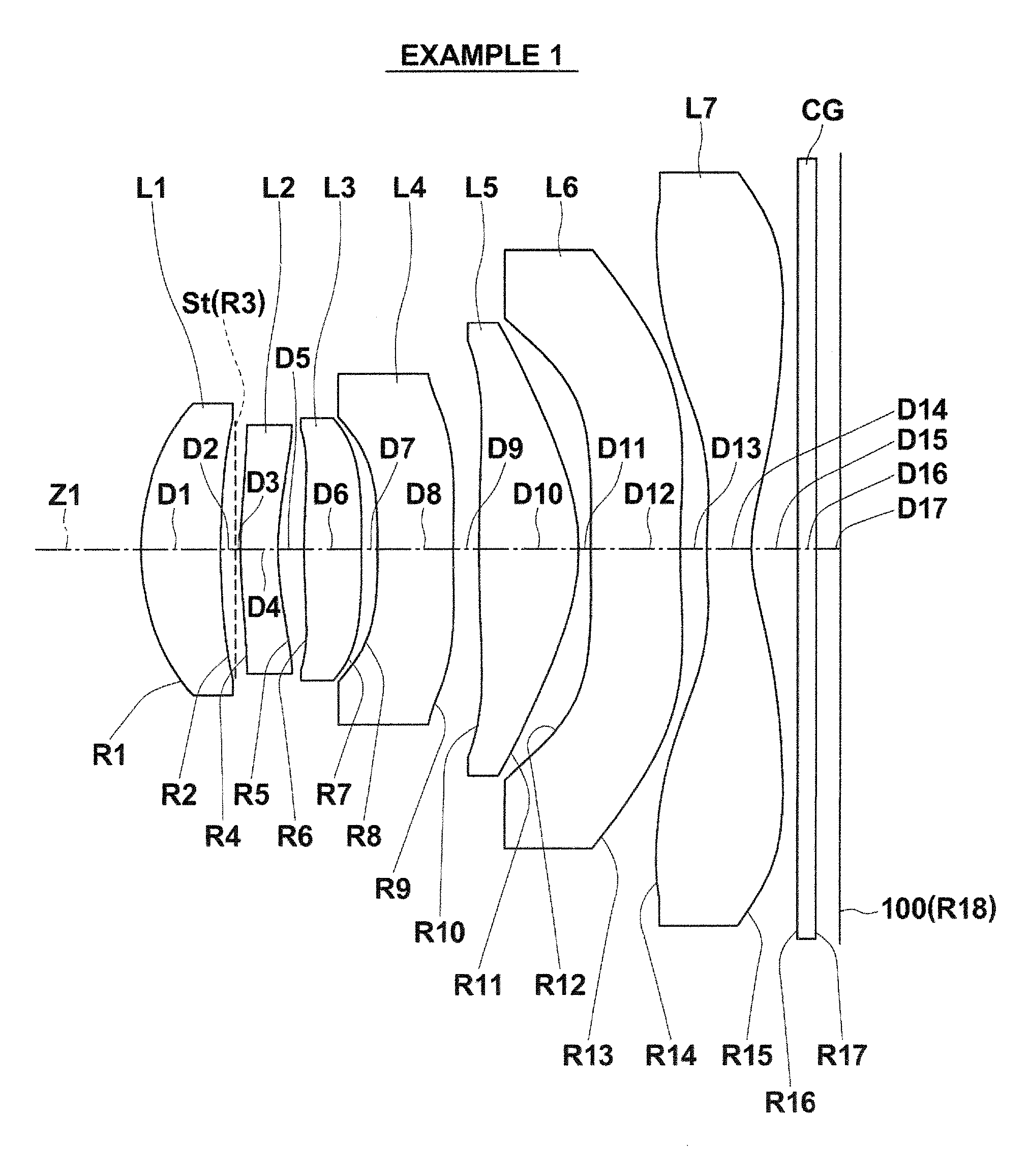
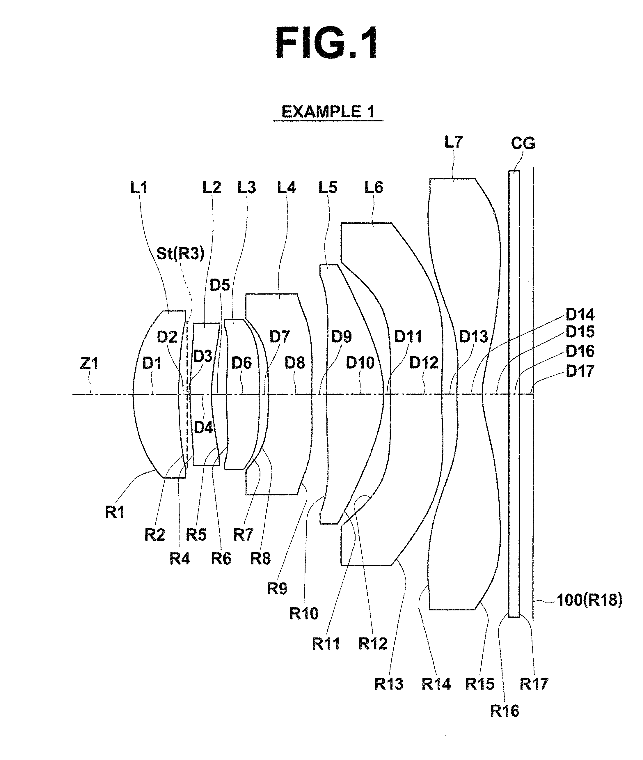
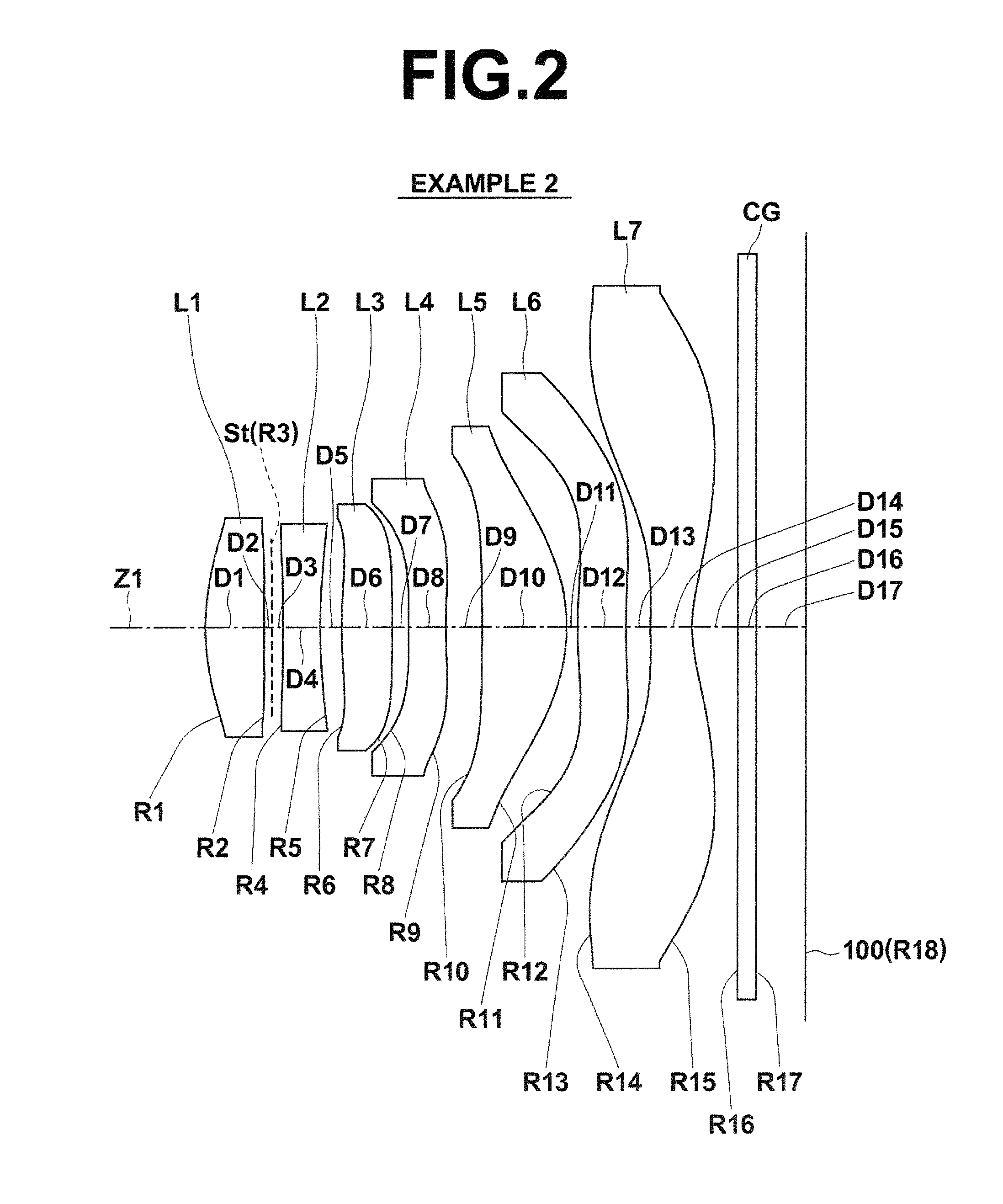
[0041]FIG. 1 illustrates a first example of the configuration of an imaging lens according to an embodiment of the present invention. This example corresponds to the lens configuration of Numerical Example 1 (Table 1 and Table 2), to be described later. Similarly, FIG. 2 through FIG. 5 and FIG. 14 are sectional diagrams that illustrate second through sixth examples of lens configurations that correspond to Numerical Examples 2 through 6 (Table 3 through Table 12). In FIG. 1 through FIG. 5 and FIG. 14, the symbol Ri represents the radii of curvature of ith surfaces, i being lens surface numbers that sequentially increase from the object side to the image side (imaging side), with the surface of a lens element most toward the object side designated as first. The symbol Di represents the distances between an ith surface and an i+1st surface along an optical axis Z...


PUM


Abstract

An imaging lens substantially includes seven lenses, constituted by: a first lens having a positive refractive power and a convex surface toward an image side; a second lens having a negative refractive power; a third lens having a positive refractive power; a fourth lens; a fifth lens having a positive refractive power; a sixth lens; and a seventh lens having a negative refractive power, a concave surface toward an image side, and at least one inflection point in the surface toward the image side; provided in this order from an object side. All of the first lens through the seventh lens are single lenses.

Description

CROSS REFERENCE TO RELATED APPLICATIONS[0001]The present application claims priority under 35 USC §119 to Japanese Patent Application No. 2013-138595 filed on Jul. 2, 2013 and Japanese Patent Application No. 2014-011158 filed on Jan. 24, 2014. Each of the above applications is hereby expressly incorporated by reference, in its entirety, into the present application.TECHNICAL FIELD[0002]The present invention is related to a fixed focus imaging lens for forming optical images of subjects onto an imaging element such as a CCD (Charge Coupled Device) and a CMOS (Complementary Metal Oxide Semiconductor). The present invention is also related to an imaging apparatus provided with the imaging lens that performs photography such as a digital still camera, a cellular telephone with a built in camera, a PDA (Personal Digital Assistant), a smart phone, and a portable gaming device.BACKGROUND ART[0003]Accompanying the recent spread of personal computers in households, digital still cameras capa...

Claims


Application Information

Patent Timeline
IPC IPC(8): G02B13/00
CPCG02B13/0045G02B9/64
Inventor SHINOHARA, YOSHIKAZUISHII, YOSHIAKI
Owner JIANGXI OFILM OPTICAL CO LTD
Why Eureka
Try Eureka