Method and device for temporary emergency vessel anastomoses

a technology of emergency vessel and anastomosis, which is applied in the field of treating vascular hemorrhage, can solve the problems of exsanguination and death of patients, severe blood loss, and loss of blood, and achieve the effects of preventing further damage to the vessel, and maintaining hemostasis

Inactive Publication Date: 2015-01-08
BUCKMAN JR ROBERT F +2
View PDF0 Cites 29 Cited by
  • Summary
  • Abstract
  • Description
  • Claims
  • Application Information

AI Technical Summary

Benefits of technology

[0017]A dual tube shunt may also be utilized where the vessel or lumen has been severed and not merely damaged. This configuration consists of two identical tubes, each for insertion into one of the severed portions of the vessel or lumen. Each of the tubes may have their own obturators. Each tube is inserted into an end of the damaged blood vessel. The obturators are, if appropriate, removed from the tube members and the shunts and the shunt components are sealably attached to each other. Quick release type connections such as bayonet mounts or snap clips facilitate bringing the two ends of the shunt together. Gaskets or fluid-tight seals at the interface between the quick-release connections prevent blood or fluid loss once the shunts are connected together.
[0018]A method of insertion of the shunt within the vasculature is also disclosed. In the case where the vessel is fully severed, a surgical incision is made to access the two vessel ends. The two vessel ends are brought to within proximity of each other. A large clamp or clamps are applied to maintain the two vessel ends within close proximity during the procedure and to maintain hemostasis. The obturator of a shunt end is inserted into one of the vessel ends and the obturator of the other shunt end is inserted into the second vessel end. Clamps are applied around the blood vessel ends to maintain the shunt ends within the vessel. The two obturators are removed, the two shunt e...

Problems solved by technology

When a blood vessel becomes wounded or severed, the loss of blood must be stopped or severe blood loss will occur.
Severe blood loss could lead to exsanguination and death of the patient.
It could also lead to shock and a cascade of deteriorating physiological conditions with negative short and long-term effects on the patient.
In addition, the tiss...

Method used


Image

  • Method and device for temporary emergency vessel anastomoses
  • Method and device for temporary emergency vessel anastomoses
  • Method and device for temporary emergency vessel anastomoses

Examples


Embodiment Construction

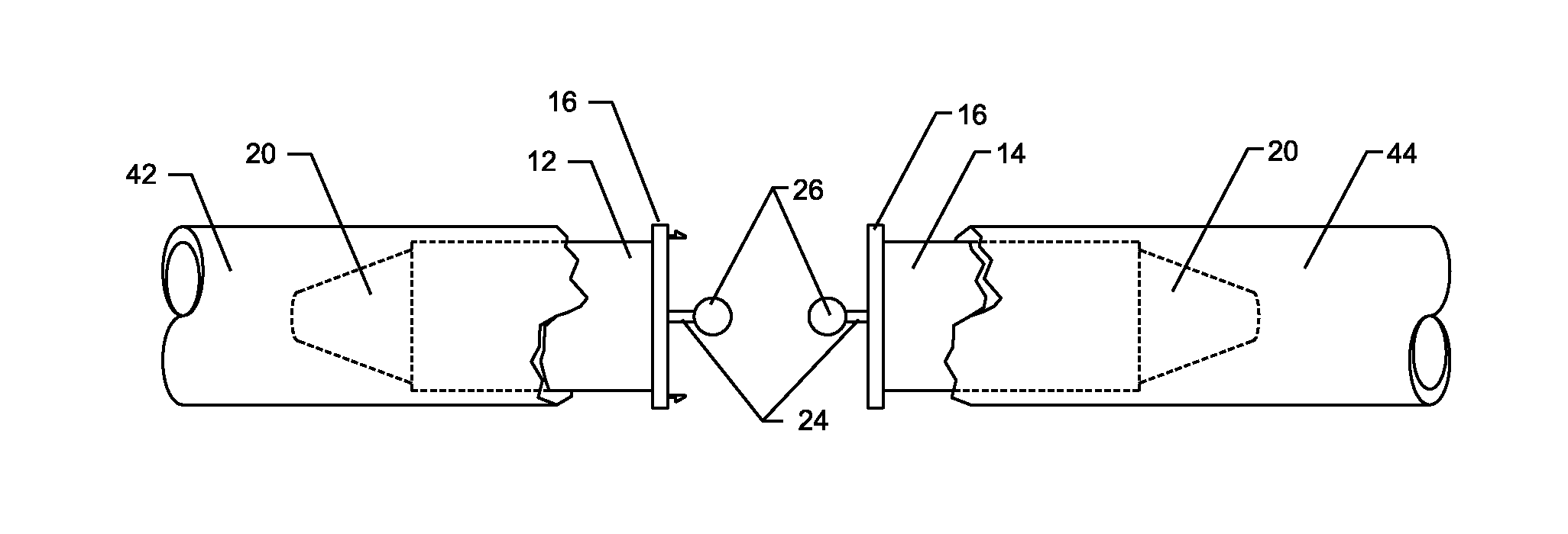
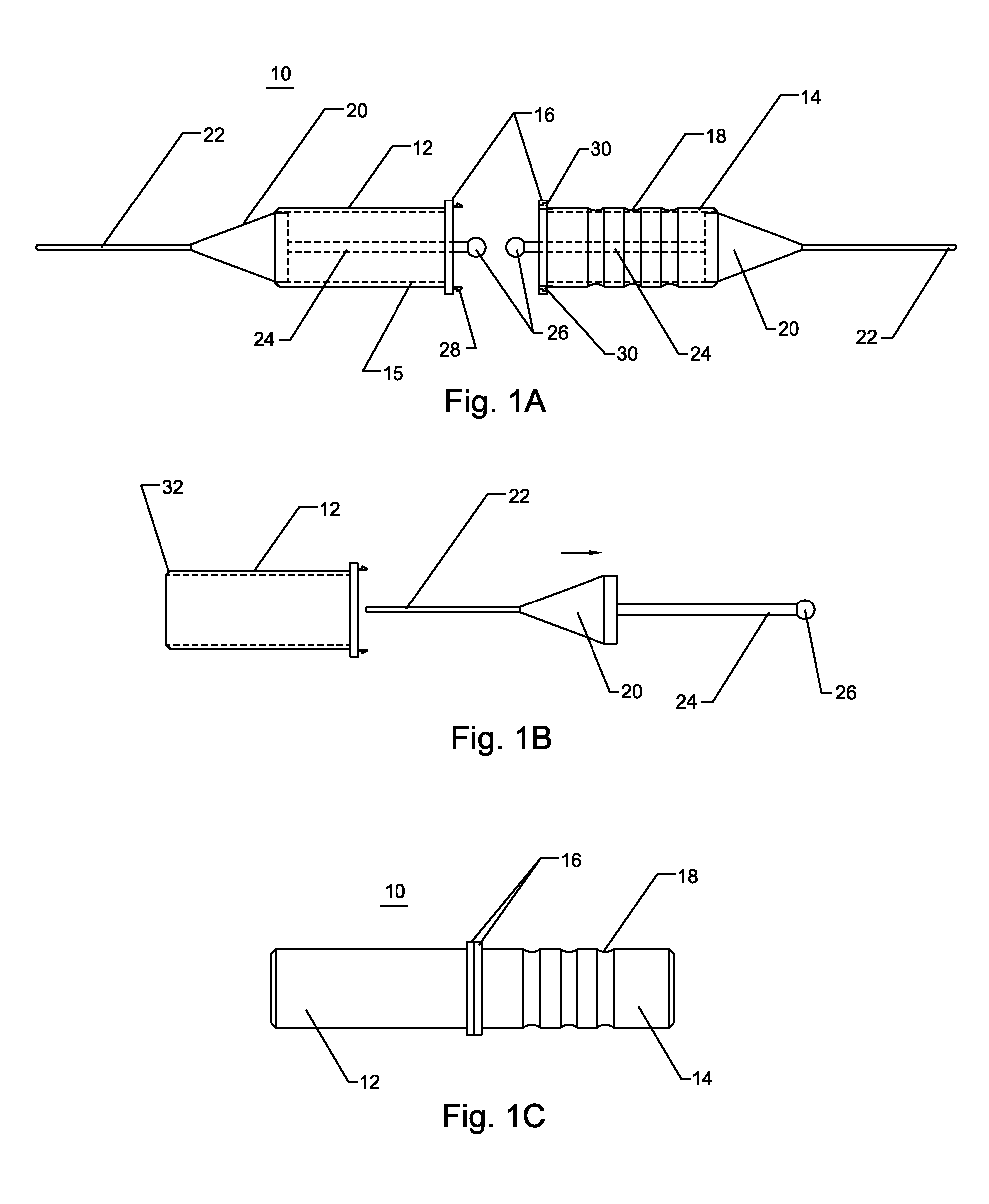
[0049]FIG. 1A illustrates a shunt 10 of the present invention comprising an axially elongate left tube 12, an axially elongate right tube 14, a plurality of flanges 16, a plurality of optional friction detents 18, a plurality of obturators 20, a plurality of optional guidewires 22, a plurality of obturator rods 24, a plurality of obturator handles 26, a plurality of locking pins 28, and a plurality of locking recesses 30. The left tube and the right tube further comprise an inner surface 15.

[0050]Referring to FIG. 1A, the left tube 12 and right tube 14 are affixed to the flanges 16. The interior surface 15 of the right tube and the left tube is integral to the left and right tubes, respectively, or it may be adhered to these tubes. The friction detents 18 are depressions or ridges circumferentially disposed on the exterior of the left tube and the right tube. The obturators 20 have a tapered end and a blunt end with the tapered end pointing out of the tubes and at the ends away from...


PUM


Abstract

A device and method for achieving hemostasis and leakage control in vascular structures and other body ducts or vessels in an emergency room or trauma situation. The device has at least one shunt that contains an obturator on an end of the shunt. The shunt is inserted into a damaged vessel or lumen for sealing the leak or hemorrhage. Two shunts that both contain obturators on one of their ends can be inserted into two different vessels or lumens when the vessel or lumen has been severed. The obturators allow for the improved ease of insertion into the vessel or lumen. The two shunts are then releasably attached to restore fluid communication through the vessel or lumen. The shunt is placed temporarily within the patient and then removed when definitive repair can be achieved by a qualified physician.

Description

PRIORITY CLAIM[0001]This application is a continuation of U.S. patent application Ser. No. 12 / 070,697, now U.S. Pat. No. 8,480,693, which is a continuation of U.S. patent application Ser. No. 10 / 703,220, filed on Nov. 5, 2003, now U.S. Pat. No. 7,335,215, which claims priority benefit under 35 USC §119(e) from U.S. Provisional Application No. 60 / 424,038 filed Nov. 5, 2002.FIELD OF THE INVENTIONS[0002]The inventions described below relate the field of treating vascular hemorrhage via anastomoses of severed or damaged vessels in an emergency room or trauma situation.BACKGROUND OF THE INVENTIONS[0003]As recently as the early 1990s, surgical operations for trauma were directed at the anatomic repair of all injuries at time of the initial operation. It was observed during these exercises that many patients became hypothermic, acidotic, and coagulopathic. Patients showing these three signs often died. Death often occurred in the operating room due to exsanguination, or postoperatively, du...

Claims


Application Information

Patent Timeline
IPC IPC(8): A61B17/11A61M25/00
CPCA61M25/0021A61B17/11A61B17/12A61B17/122A61B2017/1107A61B2017/1132A61B2017/12004A61B2090/0807
Inventor BUCKMAN, JR., ROBERT F.LENKER, JAY A.KOLEHMAINEN, DONALD J.
Owner BUCKMAN JR ROBERT F
Why Eureka
Try Eureka