
Speed change control system and speed change control method for hybrid vehicle

Active Publication Date: 2015-01-08
TOYOTA JIDOSHA KK
View PDF5 Cites 13 Cited by
  • Summary
  • Abstract
  • Description
  • Claims
  • Application Information

AI Technical Summary

Benefits of technology

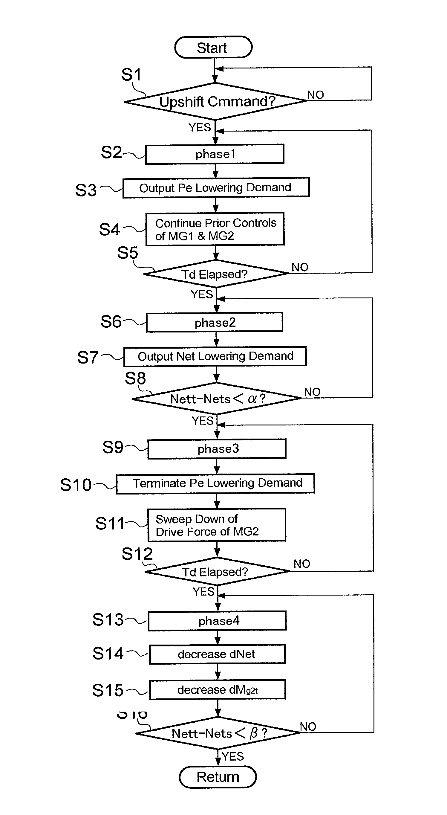
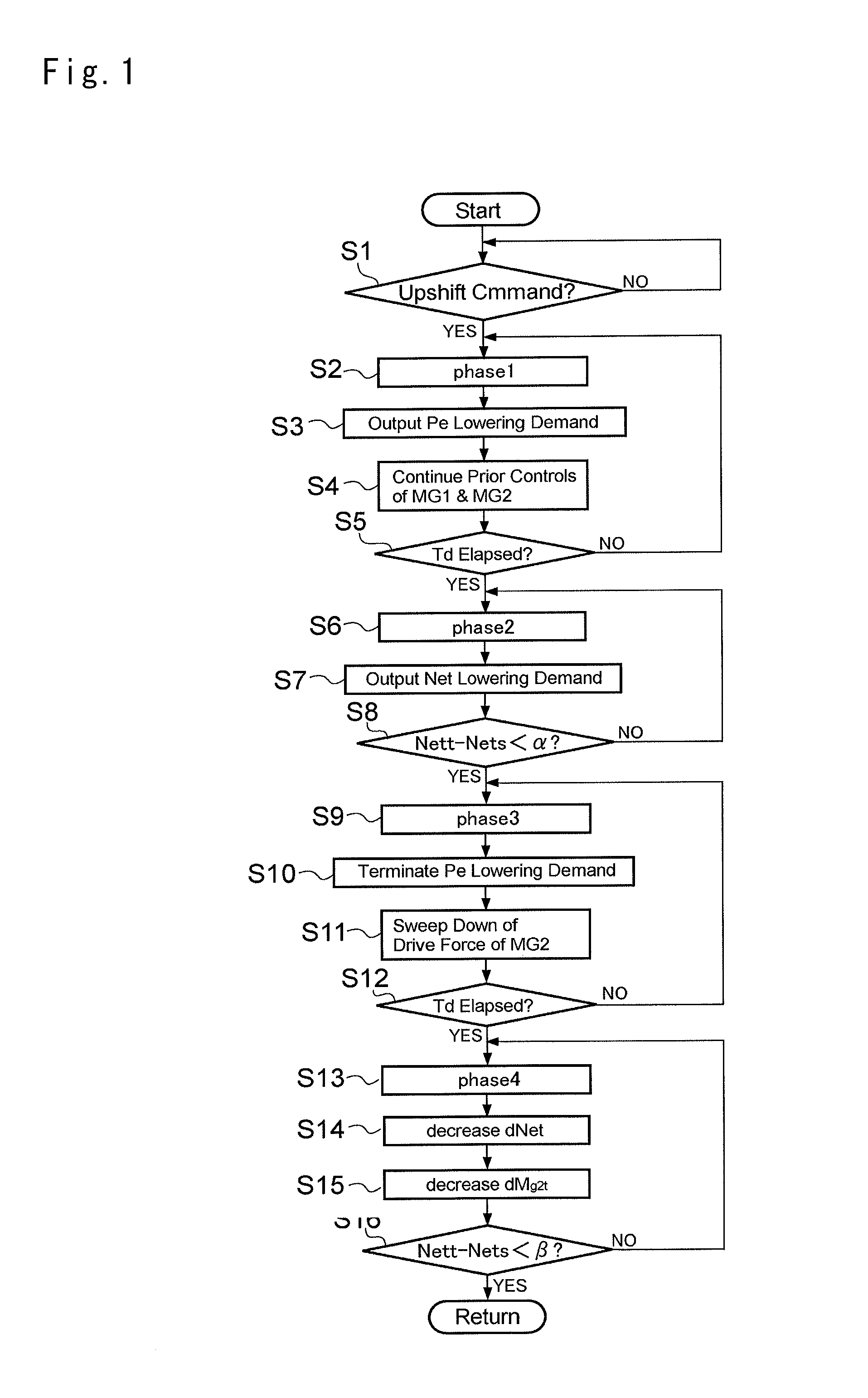
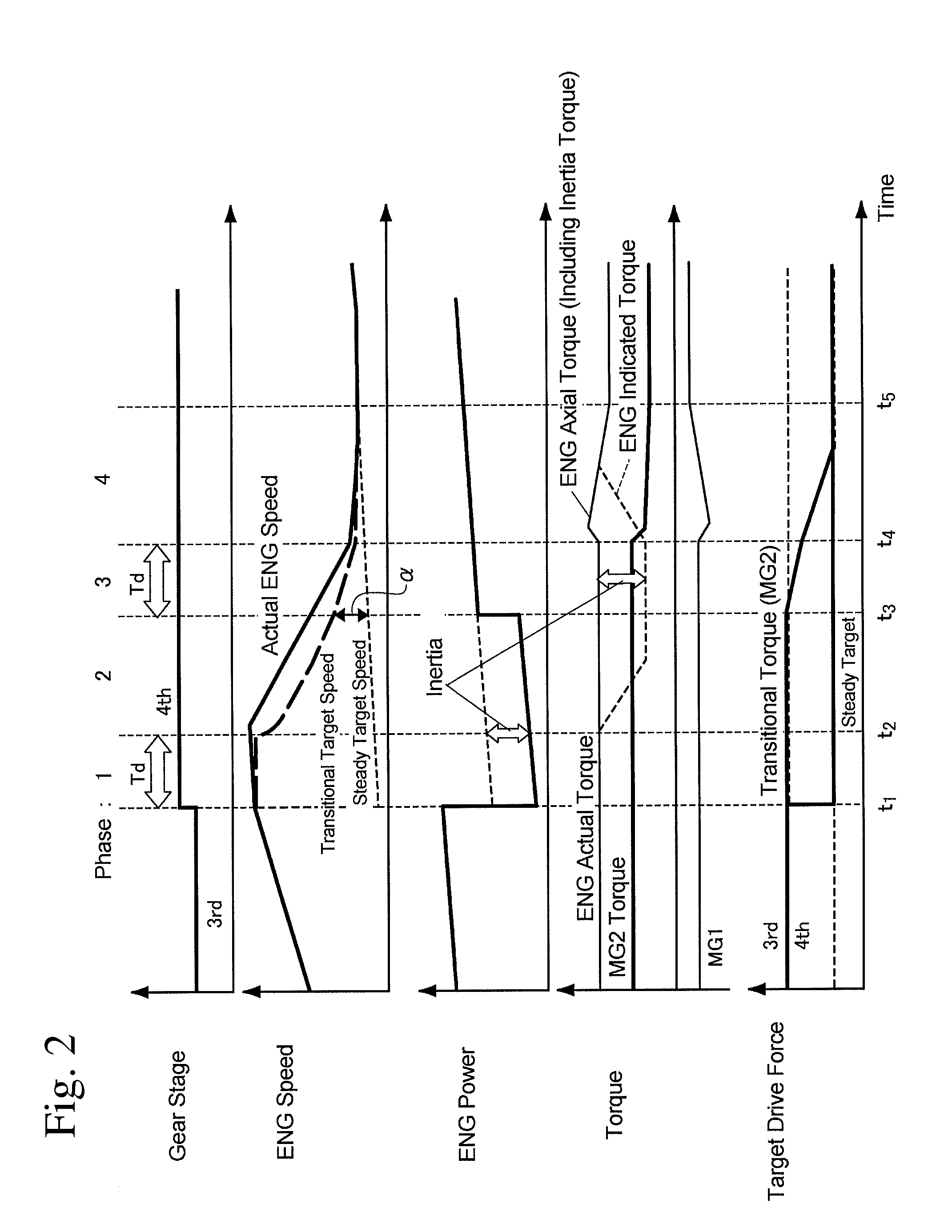
The present invention is a system for controlling speed change in a two-motor hybrid vehicle. It is designed to prevent overcharging and over discharging of the battery and to reduce shocks during the speed change operation. The system achieves this by controlling the motors in a way that avoids overloads and maintains electric balance. This results in a smooth and quick speed change without causing any uncomfortable feeling and shortens the time required for the change.

Problems solved by technology

However, such charging and discharging of the storage device may be restricted depending on the condition.
In addition, an inertia torque is generated in accordance with an inertia moment as a result of changing the engine speed, and such inertia torque may become load on the storage device and may cause a control delay.
However, the torque of the generator may be limited depending on a charging capacity of the electric storage device.
According to the teachings of Japanese Patent Laid-Open No. 2008-179291, therefore, a required power for the engine is limited in accordance with inertia energy resulting from lowering the engine speed.
If a response delay during changing the engine speed is compensated by the motor, a generation amount of the motor is increased and this may cause an overcharging of a battery.
Otherwise, an over discharging may be induced to increase the motor torque.
However, it may take time to consume the inertia energy resulting from lowering the engine speed.
Therefore, a reduction in the engine speed, that is, the speed change operation may be delayed.
Therefore, the reduction in the engine speed, that is, the speed change operation may also be delayed.
However, in the hybrid vehicle taught by Japanese Patent Laid-Open No. 2011-105240, the engine speed is not lowered aggressively.
This means that the control response to change the engine speed may not be improved.
Such technical problem may also not be solved by the teachings of Japanese Patent Laid-Opens Nos. 2005-315084 and 2006-63865.
Therefore, an increase in the engine speed is delayed inevitably.
In addition, since the control is carried out without taking into consideration the inertia moment of the engine, the response delay may be worsened when changing the engine speed stepwise by a manual operation.

Method used


Image

  • Speed change control system and speed change control method for hybrid vehicle
  • Speed change control system and speed change control method for hybrid vehicle
  • Speed change control system and speed change control method for hybrid vehicle

Examples


Embodiment Construction

[0037]The hybrid vehicle or a drive unit thereof to which the present invention is applied is provided with a device for changing an engine speed or a substantial speed ratio continuously, and the speed change control system and method of the present invention are configured to change the engine speed or the substantial speed ratio stepwise. Referring now to the accompanying figures, a power train of the hybrid vehicle will be explained first of all with reference to FIG. 9. In FIG. 9, there is shown an example of a two-motor type hybrid drive unit, and a power of an engine (ENG) 1 is distributed to an output shaft 3 side and to a first motor-generator (MG1) 2 side through a power distribution device 2. An internal combustion engine such as a gasoline engine and a diesel engine may be used as the engine 1, and an output element of the engine 1 such as a crankshaft is connected with the power distribution device 2. In the example shown in FIG. 9, a single-pinion type planetary gear u...


PUM


Abstract

A speed change control system for a hybrid vehicle comprised of a first motor-generator, a differential mechanism that distributes a power of an engine to the first motor-generator and to an output member and that changes an engine speed in accordance with a speed of the first motor-generator, and a second motor-generator that exchanges a torque with any of wheels. The speed change control system comprises: a first power control means that outputs a command for changing an engine power in a direction to expedite a change in an engine speed, at the beginning of a speed change for changing the engine speed stepwise; a first speed control means that continues controls of the first and the second motor-generators as before the speed change, during a period from a point at which the first power control means outputs the command for changing the engine power to a point at which a response delay of the engine elapses; a second speed control means that controls the first motor-generator in a manner such that the engine speed is changed in a direction to be changed by the change in the engine power, after a lapse of the response delay of the engine; and a second power control means that outputs a command for changing the engine power to a power to be achieved after the speed change, when the engine speed is changed substantially to a target speed to be achieved after the speed change.

Description

TECHNICAL FIELD[0001]The present invention relates to a control system for a hybrid vehicle in which a prime mover is comprised of an internal combustion engine and a motor. More specifically, the present invention relates to a control system and method for controlling an operation of changing a speed of the engine stepwise, which is applied to a hybrid vehicle comprised of a first motor mainly controlling a speed of the engine, and a second motor mainly assisting a drive torque for propelling the vehicle.BACKGROUND ART[0002]In a two-motor type hybrid vehicle or a hybrid drive unit, a power of an internal combustion engine (i.e., an engine) is distributed by a power distribution device composed mainly of a differential mechanism to the first motor having a generating function and to an output member, and an electric power generated by the first motor is delivered to the second motor connected with the output member to operate the second motor. Thus, in the two-motor type hybrid vehi...

Claims


Application Information

Patent Timeline
IPC IPC(8): B60W20/00B60W10/08B60W10/06B60L50/16
CPCB60W20/10Y10S903/93B60W10/08B60W10/06B60K6/445B60K6/547B60W20/00B60W30/19F02D29/02B60W2710/0644Y02T10/62Y02T10/72
Inventor HONDA, TOMOYUKIMATSUNAGA, HITOSHISHIMURA, SOUITIROUMASUNAGA, SEIJIKATSUMATA, MUNEHIRO
Owner TOYOTA JIDOSHA KK
Learn More