Method for forming forged parts

a technology of forged parts and forged parts, applied in forging/pressing/hammering equipment, forging/hammering/pressing machines, forging/pressing/hammering machines, etc., can solve the problems of increased environmental impact, not insignificant cost increase, and cast products, and achieve efficient material displacement, high forming force, and precise shaping of forged parts

Active Publication Date: 2015-01-15
CARL DAN PEDDINGHAUS
View PDF4 Cites 4 Cited by
  • Summary
  • Abstract
  • Description
  • Claims
  • Application Information

AI Technical Summary

Benefits of technology

[0010]Preferably, the tool which is inserted into the forged part during forming is a punch (mandrel) or hollow punch (hollow mandrel). By the use of a punch or hollow punch, high forming forces can be applied, which lead to efficient material displacement during forming and a complete filling of the die. A hollow punch additionally enables a particularly precise shaping of the forged part at the point of insertion and can thus be employed particularly effectively to determine the end contour.
[0011]According to a preferred embodiment, secondary formed elements of the finished forged part are formed by the tool and/or tools. Secondary formed elements within the meaning of the present application are shape features of the forged part surface, which cannot be produced or only with difficulty with forging by dies (die halves moved against each other), for example the seats for bearing shells on truck steering knuckles. In particular the formation of secondary formed elements necessitated in the prior art material-removing machining processes which not only increased the material used but also extended the processing times. By forming such secondary formed elements by means of the tool/tools, a great deal of material and accordingly time can be saved.
[0012]In a particularly preferred embodiment, the forming is essentially carried out at the temperature of the preceding pre-forging step. Here it is advantageous that owing to the high temperatures still from the forging process, an essentially power-saving form...

Problems solved by technology

Both aspects lead to a not insignificant cost increase as well as an increased environmental impact.
While it would be conceivable from a material-saving point of view to cast such components, cast products, however, have clear ...

Method used


Image

  • Method for forming forged parts
  • Method for forming forged parts
  • Method for forming forged parts

Examples


Embodiment Construction

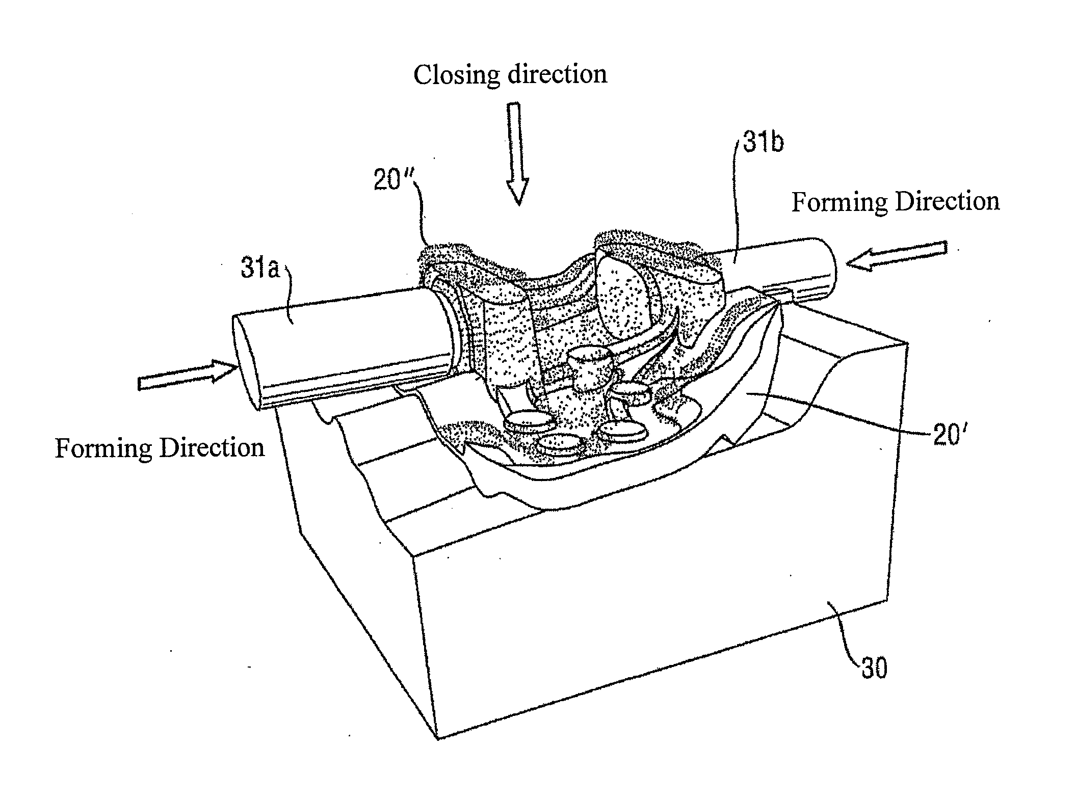
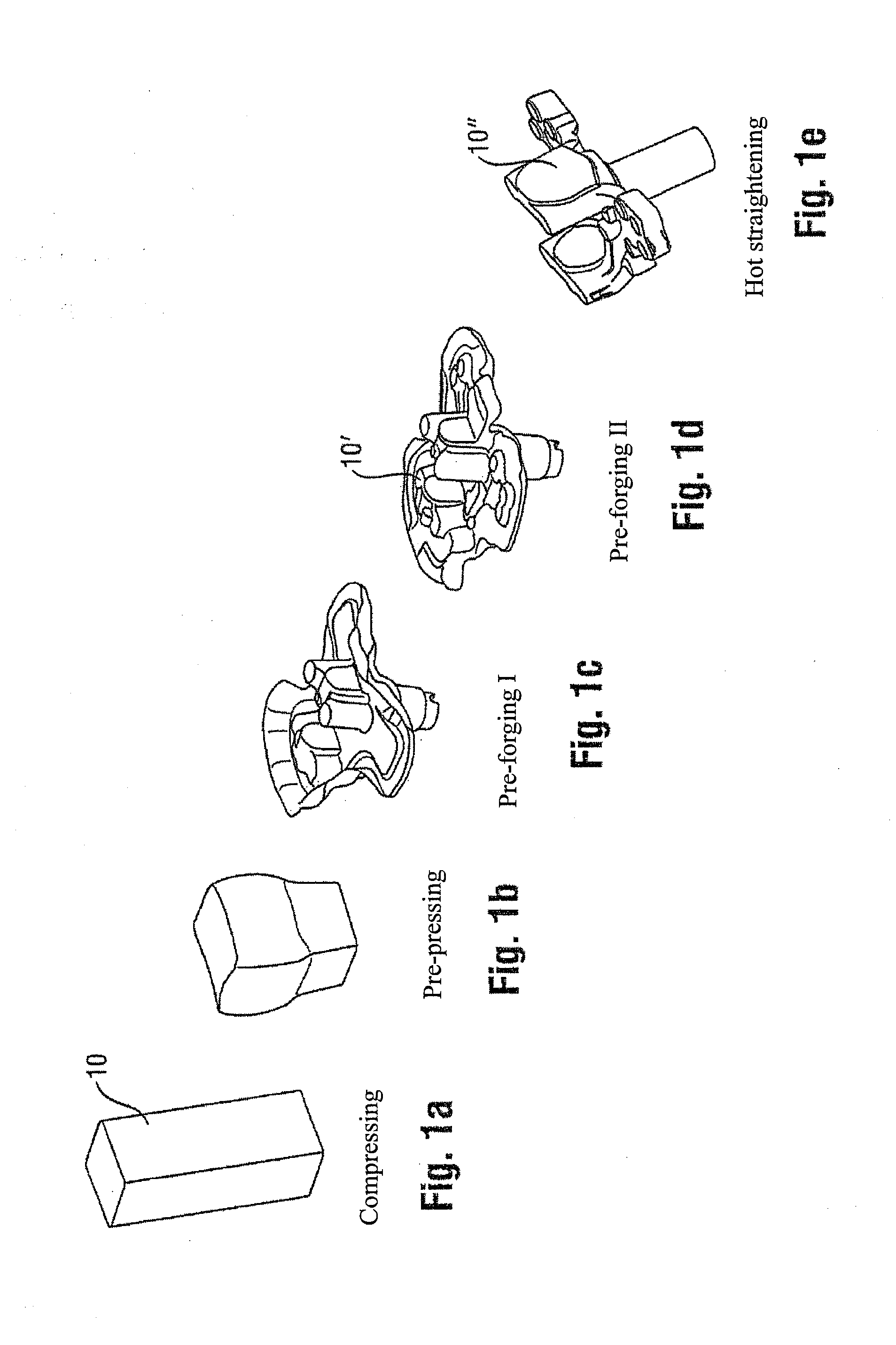
[0021]FIG. 1 schematically shows the course of a production procedure of a truck steering knuckle according to the prior art. A blank 10 made of steel is first compressed, pre-pressed and subjected to a first step of pre-forging (FIGS. 1a to c), the essential outer geometry of the component being formed being produced. During the subsequent second pre-forging step (FIG. 1d), the detailed outer contours of this intermediate product 10′ are produced by the die (but not larger than the pre-given end contour). In the final deburring or hot straightening step (FIG. 1e), the excess forging material is then removed such that the forged finished product 10″ is obtained. Since by means of the forging process, however, no complicated three-dimensional contours can be formed, such as, for example, lateral notches for bearing shells, the completed forged part 10″ must still be mechanically reworked, that is by machining. The excess material accumulated during reworking thus increases the raw ma...


PUM

PropertyMeasurementUnit
Temperatureaaaaaaaaaa
Volumeaaaaaaaaaa

Abstract

A method according to the invention for producing forged parts with a prescribed end contour comprises the following steps: pre-forging of a blank in order to obtain a forged part and subsequent reshaping of the forged part in a die, wherein one or a plurality of tools are inserted into the forged part during the reshaping and, in the process, the material of the forged part is displaced in a manner such that the specified end contour is obtained.

Description

TECHNICAL FIELD[0001]The present invention relates to a method for forming forged parts, in particular for the formation of so-called secondary formed elements on the forged parts. Examples of such forged parts are, for example, steering knuckles for commercial vehicles.PRIOR ART[0002]In the automotive industry as well as generally in the field of transport and commercial vehicles (that is, for example, cars, trucks, construction vehicles, trains), highly stressed forged components having complex geometries are being increasingly employed. At the same time, the requirements for the precision of the components have also increased. When producing such forged parts, such as, for example, the steering knuckles for commercial vehicles mentioned at the outset, in the current prior art a raw part is first generated by forging, which after deburring is again mechanically reworked, that is by machining, to form desired features such as bearing seats with the necessary precision and to thus a...

Claims


Application Information

Patent Timeline
IPC IPC(8): B21J5/00B21J13/00B21J5/02
CPCB21J5/02B21J13/00B21J5/008B21J5/025B21J9/027B21K1/12
Inventor BACHMANN, MARKUS
Owner CARL DAN PEDDINGHAUS
Why Eureka
Try Eureka