Vibration isolation apparatus, method of isolating vibration, lithography apparatus, and method of producing device

Active Publication Date: 2015-01-15
CANON KK
View PDF22 Cites 5 Cited by
  • Summary
  • Abstract
  • Description
  • Claims
  • Application Information

AI Technical Summary

Benefits of technology

This patent is about a device that reduces vibration and improves the performance of vibration isolation compared to using a fixed negative constant. The device achieves this by reducing the natural frequency.

Problems solved by technology

In apparatuses that perform precision measurement such as lithography apparatuses for manufacturing a semiconductor, atomic force microscopes, and scanning electron microscopes, measurement errors may be caused by receiving external vibration such as floor vibration.

Method used


Image

  • Vibration isolation apparatus, method of isolating vibration, lithography apparatus, and method of producing device
  • Vibration isolation apparatus, method of isolating vibration, lithography apparatus, and method of producing device
  • Vibration isolation apparatus, method of isolating vibration, lithography apparatus, and method of producing device

Examples


first embodiment

Configuration of Apparatus

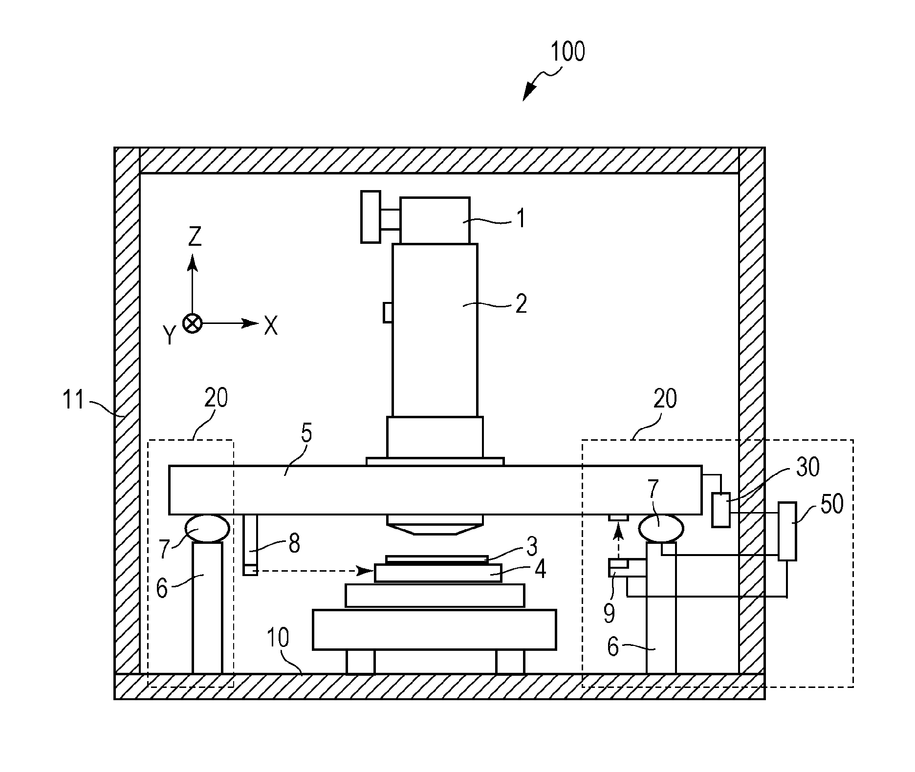
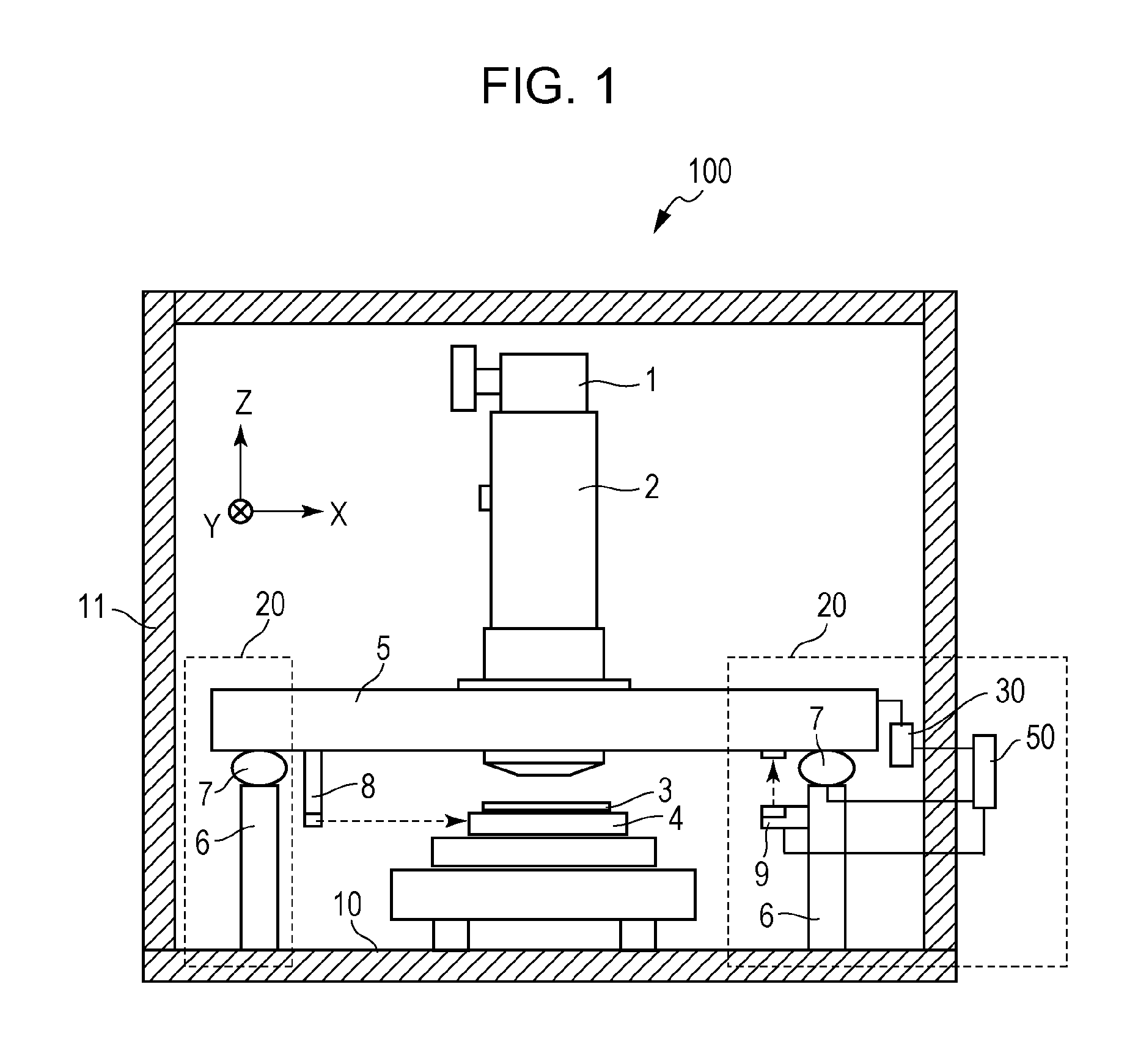
[0017]FIG. 1 illustrates the configuration of a drawing apparatus (lithography apparatus) 100 that includes vibration isolation apparatuses 20 according to a first embodiment of the present invention disposed therein. Although the vibration isolation apparatuses 20 are disposed in the drawing apparatus 100 that draws patterns by using a single focused electron beam in an example described in the first embodiment, the number of electron beams are not limited to this. The drawing apparatus may use a plurality of electron beams. The vibration isolation apparatus according to the present embodiment can also be applied to any of a variety of apparatuses for which high vibration isolation performance is required such as lithography apparatuses, in which a various beams are radiated or which use an imprint technology, and precision measurement sensors.

[0018]An electron source 1 emits an electron beam, which is directed to a substrate 3 by an electro-optical system...

second embodiment

[0053]Next, a vibration isolation apparatus according to a second embodiment is described with reference to FIG. 6. The second embodiment relates to a vibration isolation apparatus 70 that performs vibration isolation in a single axial direction (X-axis direction). A securing member 12, an air slider 40, and the displacement sensor 9 are disposed on a mounting surface 65. A guide 41 is inserted through the air slider 40. In the present embodiment, the guide 41 serves as the object. A coil spring 13 is connected to the tip end of the guide 41. The coil spring 13 serves as a support unit that elastically supports the guide 41. Another end of the coil spring 13 is connected to the securing member 12.

[0054]The actuator 30 is connected to the guide 41. The actuator 30 applies a negative spring force similarly to the actuator 30 in the first embodiment. The actuator 30 also positions the guide 41 at a predetermined position similarly to the mount 7 in the first embodiment. Displacement of...

example

[0056]An example of the vibration isolation apparatus 70 according to the present embodiment is described. The actuator 30 used a linear motor. The displacement sensor 9 used a laser displacement meter.

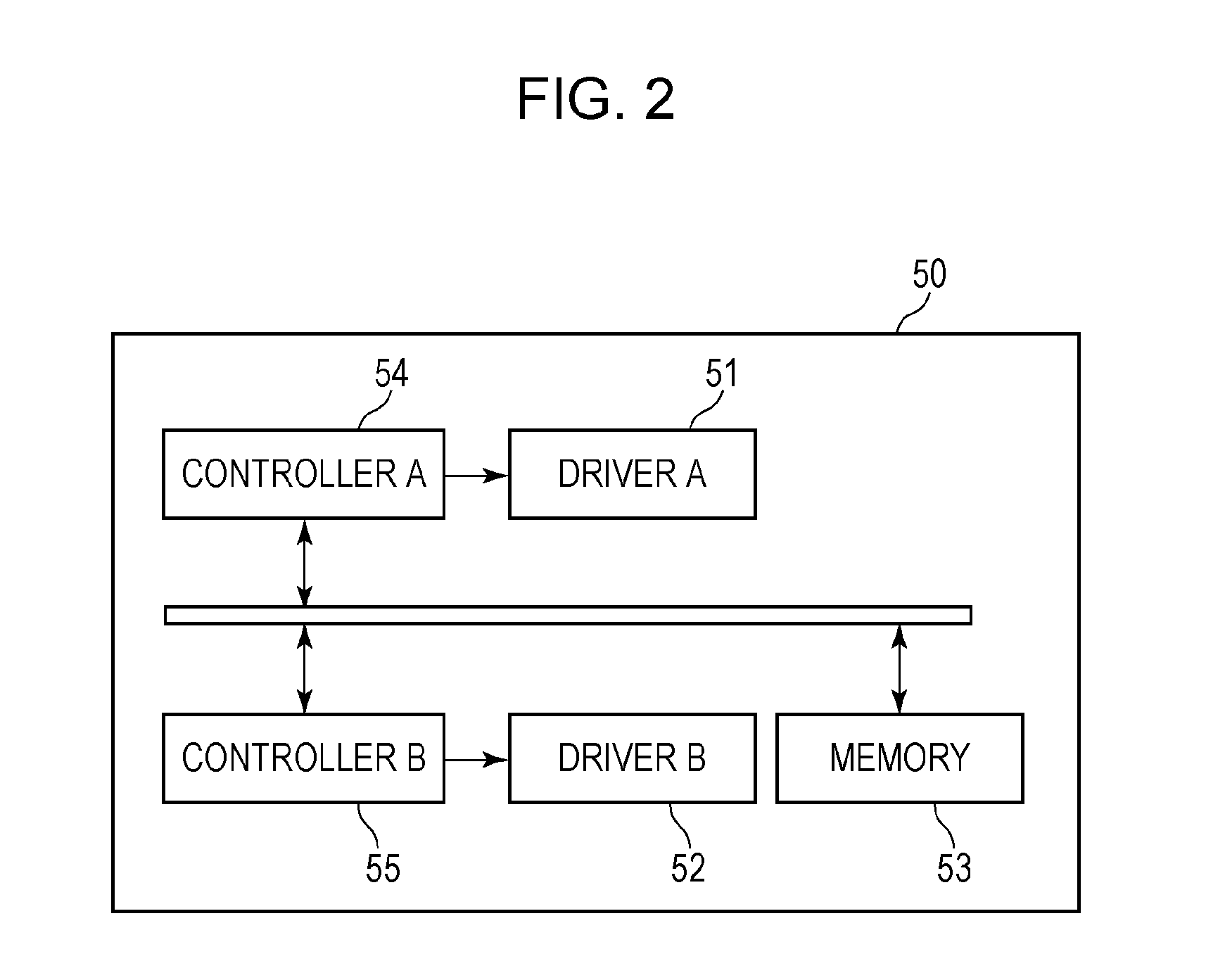
[0057]Initially, the reference table of the present embodiment was created by the aforementioned method, and the spring constant K for each measurement displacement x was calculated. A reference function K=f(x) was obtained by approximating a graph representing the spring constant K for each displacement x by a second order polynomial. The reference function K=f(x) was stored in the memory 53.

[0058]Next, in order to check the vibration isolation performance of the vibration isolation apparatus 70 when external vibration is applied to the guide 41, vibration was applied to the guide 41 through the actuator 30, and the frequency response was measured. At this time, by using the actuator 30, not only the guide 41 was vibrated corresponding to the frequency, but also the negative spring f...


PUM

PropertyMeasurementUnit
Forceaaaaaaaaaa
Displacementaaaaaaaaaa

Abstract

A vibration isolation apparatus includes a support unit that elastically supports an object to a mounting surface, a measurement sensor that measures a displacement of the object relative to the mounting surface, a drive unit that drives the object, and a storage unit. The storage unit stores data indicating a relationship between the displacement of the object and information that indicates a non-linear force produced by an elastic element including a support unit and that corresponds to the displacement. The drive unit drives the object in accordance with the displacement of the object and the data.

Description

BACKGROUND OF THE INVENTION[0001]1. Field of the Invention[0002]The present invention relates to a vibration isolation apparatus, a method of isolating vibration, a lithography apparatus that includes the vibration isolation apparatus disposed therein, and a method of producing a device.[0003]2. Description of the Related Art[0004]In apparatuses that perform precision measurement such as lithography apparatuses for manufacturing a semiconductor, atomic force microscopes, and scanning electron microscopes, measurement errors may be caused by receiving external vibration such as floor vibration. In order to address this, vibration isolation is required for these apparatuses so as to minimize transmission of external vibration to the apparatuses.[0005]In a known related-art vibration isolation apparatus for precision measurement, an object is supported by an air spring, the natural frequency of which is smaller than that of a metal spring and which can suppress vibration of a large fre...

Claims


Application Information

Patent Timeline
IPC IPC(8): F16F15/04F16M11/18
CPCF16F2226/023Y10T29/49764F16M11/18F16F15/04G03F7/709
Inventor SHIBATA, YUGO
Owner CANON KK
Why Eureka
Try Eureka