Actuator for damping low-frequency oscillations

a low-frequency oscillation and actuator technology, applied in electrical apparatus, dynamo-electric machines, mechanical energy handling, etc., can solve the problems of limited frequency operating range of actuator systems, inability to further reduce spring stiffness, and poor control properties, and achieve limited service life

Active Publication Date: 2015-01-15
CONTITECH VIBRATION CONTROL
View PDF4 Cites 20 Cited by
  • Summary
  • Abstract
  • Description
  • Claims
  • Application Information

AI Technical Summary

Benefits of technology

[0031]This embodiment is advantageous because, in this case too, a sliding guide or a ball guide can be used, and at the same time compact construction of the actuator is possible.
[0032]According to a further aspect of the invention, a supporting spring is provided between the actuator housing and the structure in such a way that the supporting spring has a damping effect in the longitudinal direction L when the coil oscillates.
[0033]In this advantageous embodiment of the actuator according to the invention, damping can also be achieved in the longitudinal direction L, the damping advantageously having an effect on the

Problems solved by technology

This may result in very poor control properties and also, under certain circumstances, in the oscillating mass loudly striking the actuator housing.
This currently leads to a restriction in the frequency operating range of the actuator system because the operating range of the actuator is shifted toward relatively high frequencies in order to not excite the resonant frequency fe during operation.
Since the spring system used in the linear electromagnetic actuator also has to compensate for the magnetic transverse stiffness between the coil

Method used


Image

  • Actuator for damping low-frequency oscillations
  • Actuator for damping low-frequency oscillations
  • Actuator for damping low-frequency oscillations

Examples


first embodiment

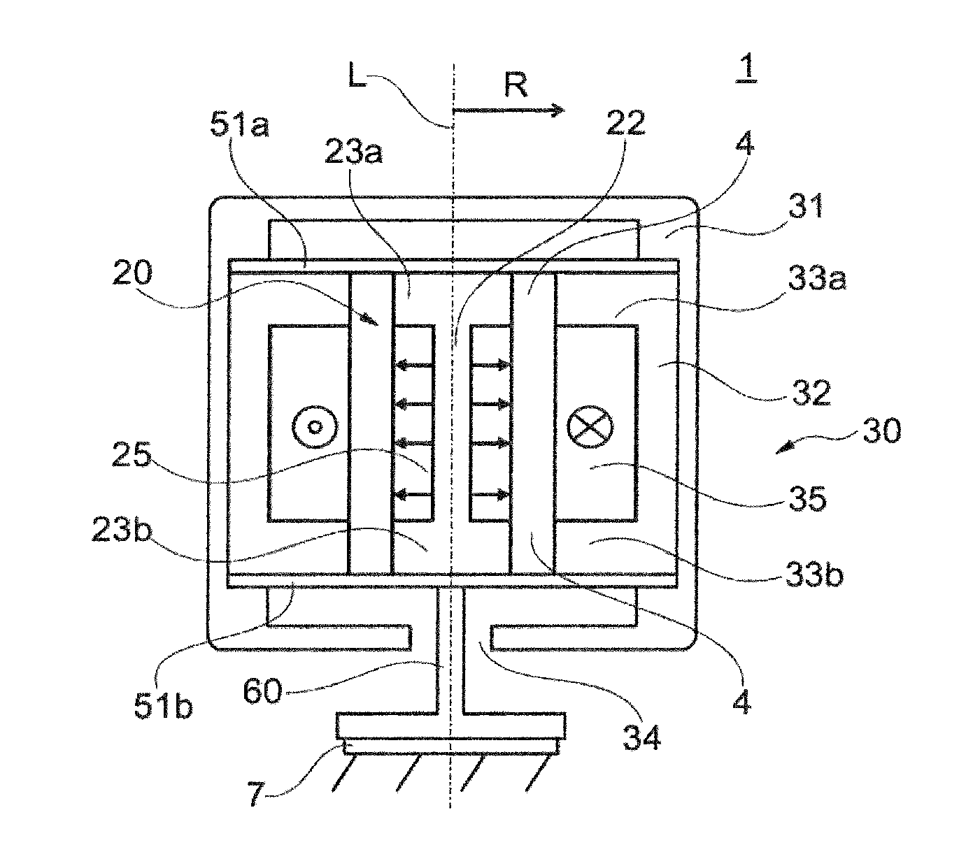
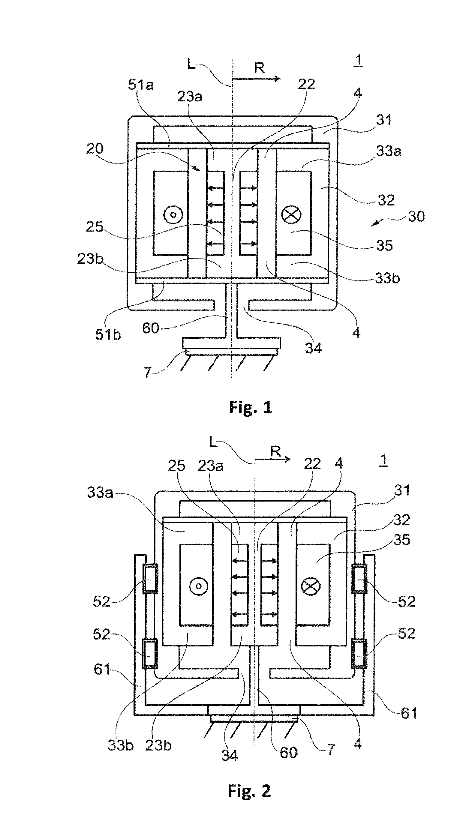
[0041]FIG. 1 is a schematic of an actuator 1 according to the invention in a The actuator 1 is a linear electromagnetic actuator 1 (linear actuator, linear motor) having a mass-spring system which can oscillate. The actuator 1 has an outer part 30 which can oscillate and which is provided around an inner stationary part 20 perpendicular to the longitudinal axis L of the actuator 1. The longitudinal axis L of the actuator at the same time forms the longitudinal axis L of the outer part 30 which can oscillate and also of the inner stationary part 20 and also represents the oscillation axis of the actuator 1.

[0042]The stationary part 20 of the actuator 1 is fixedly connected to a structure 7, into which an oscillation is intended to be introduced by the actuator 1, such as a vehicle body 7 for example, via a connecting element 60, so that oscillations of the part 30, which can oscillate, of the actuator 1 can be transmitted to the structure 7. To this end, the stationary part 20 and t...

third embodiment

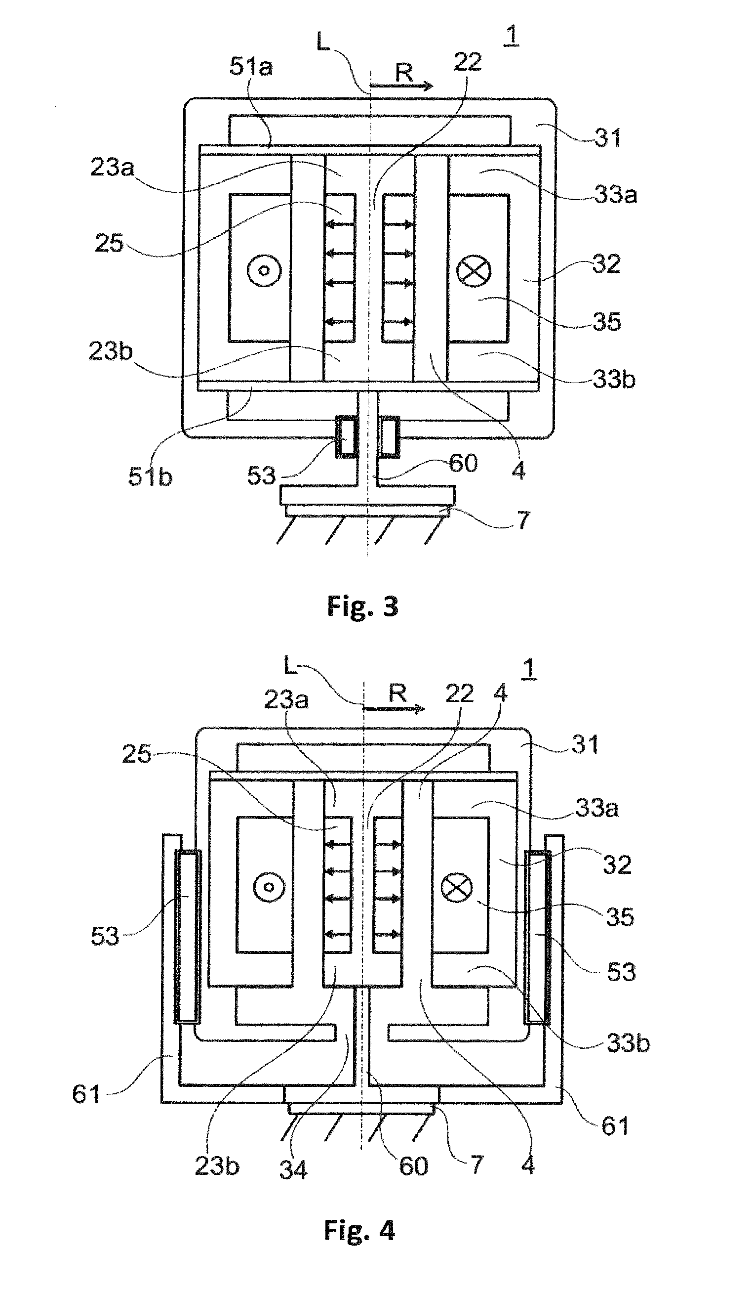
[0049]FIG. 3 shows a schematic of an actuator 1 according to the invention in a In this case, guiding in the longitudinal direction L between the part 30 which can oscillate and the stationary part 20 is realized by a sliding guide 53 or a ball guide 53 which is provided in the opening 34 between the actuator housing 31 and the connecting element 60. In this case, the sliding guide 53 or ball guide 53 can be provided as an alternative or in addition to the spring-action elements (51a, 51b) which then primarily absorb the transverse forces in the radial direction R, this otherwise likewise being assumed by the sliding guide 53 or ball guide 53; FIG. 3 shows the combination of spring-action elements (51a, 51b) with a sliding guide 53 or ball guide 53.

fourth embodiment

[0050]FIG. 4 shows a schematic of an actuator 1 according to the invention in a In this case, a sliding guide 53 or ball guide 53 is arranged between the actuator housing 31 and the lateral projection 61 of the connecting element 60.


PUM


Abstract

An actuator has an electrically conductive coil which has a longitudinal axis and windings through which a current can flow. The coil is surrounded by a highly permeable first ferromagnetic body so that the first body has projections of highly permeable ferromagnetic material above and below the coil in the longitudinal direction. The actuator has a magnet spaced apart from the coil so that a gap forms therebetween. The magnet is surrounded by a highly permeable second ferromagnetic body so that the second body has projections of highly permeable ferromagnetic material above and below the magnet in the longitudinal direction. The magnet is statically mounted with the second body and the coil is spring mounted with the first body so that the coil and first body oscillate in the longitudinal direction when an alternating current flows through the coil. The coil is outside the magnet perpendicular to the longitudinal axis.

Description

CROSS REFERENCE TO RELATED APPLICATIONS[0001]This application is a continuation application of international patent application PCT / EP2013 / 053234, filed Feb. 19, 2013, designating the United States and claiming priority from German application 10 2012 102 833.8, filed Apr. 2, 2012, and the entire content of both applications is incorporated herein by reference.BACKGROUND OF THE INVENTION[0002]Actuators of this kind are known, for example, from U.S. Pat. No. 6,476,702. The actuators contain a mass-spring system which can oscillate and which is made to oscillate when an alternating current is driven through the electrically conductive coil. The actuators are used for an extremely wide variety of purposes, for example as linear electromagnetic actuators (linear motors) in pumps, as oscillation generators or as oscillation absorbers. In the last-mentioned case, an actuator of the kind described in the introductory part is mechanically operatively connected to an oscillating component an...

Claims


Application Information

Patent Timeline
IPC IPC(8): H02K33/18H02K7/08
CPCH02K7/08H02K33/18H01F7/066
Inventor GENDERJAHN, ROBERTUHRMEISTER, BERNHARDKARKOSCH, HANS-JUERGENMARIENFELD, PETER
Owner CONTITECH VIBRATION CONTROL
Why Eureka
Try Eureka