Bi-directional data transmission method, high-frequency connector and optical connector using the same

a data transmission and high-frequency technology, applied in the direction of optics, optical light guides, instruments, etc., can solve the problems of large increase in the amount of data transmission, and no longer viable coaxial cables, etc., to achieve the effect of reducing production costs, increasing the printing space of the two circuit boards, and reducing the difficulty of quality control

Active Publication Date: 2015-01-15
NEXTRONICS ENG CORP
View PDF2 Cites 8 Cited by
  • Summary
  • Abstract
  • Description
  • Claims
  • Application Information

AI Technical Summary

Benefits of technology

[0010]The present disclosure has the following advantages. By connecting the two circuit boards through the high frequency connector, a single optical engine is used and production cost is reduced. Moreover, the difficulty of quality control is also reduced. Additionally, by connecting the two circuit boards through a high frequency connector, signals can be transmitted not only on the outer surfaces of the two circuit boards, but also on the inners sides of the two surfaces, greatly increasing the printing space of the two circuit boards, providing a more flexible printing condition.

Problems solved by technology

Due to significant increase in demands for communication and data transmission quantity, traditional coaxial cables no longer serve as viable transmission medium.
However, the optical engine and the optical fiber are main components of the connector 10′ and incur a large portion of the production cost.
However, when the amount of data transmission is greatly increased, the limited transmission speed of the FPC flexible cables 13′14′ cannot be used in high frequency transmission.
The extensions of the first circuit board 101′ and the second circuit board 102′ comprising the surface contacts increases production cost, and the soldering quality can also be problematic.

Method used


Image

  • Bi-directional data transmission method, high-frequency connector and optical connector using the same
  • Bi-directional data transmission method, high-frequency connector and optical connector using the same
  • Bi-directional data transmission method, high-frequency connector and optical connector using the same

Examples


Embodiment Construction

[0024]Unless otherwise specified, the present disclosure is not limited to the amounts and quantities mentioned in the following embodiments. The aforementioned illustrations and following detailed descriptions are exemplary for the purpose of further explaining the scope of the present disclosure. Other objectives and advantages related to the present disclosure will be illustrated in the subsequent descriptions and appended drawings.

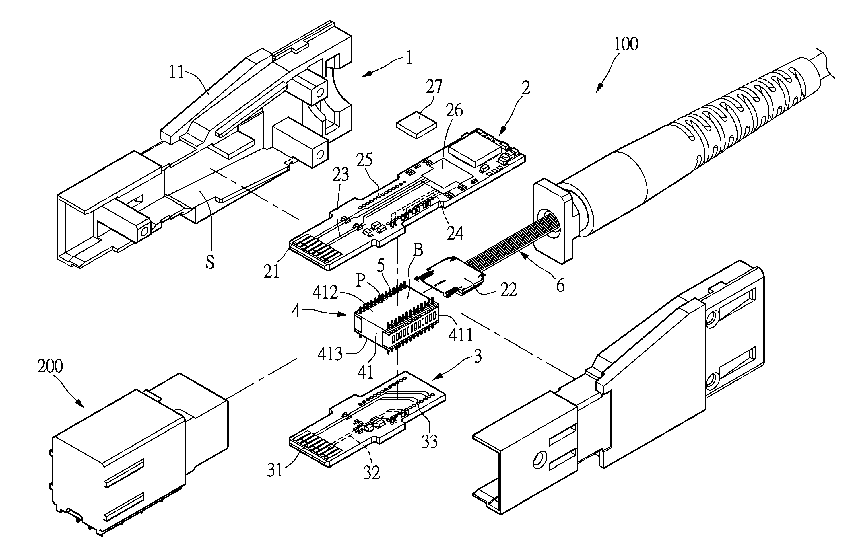
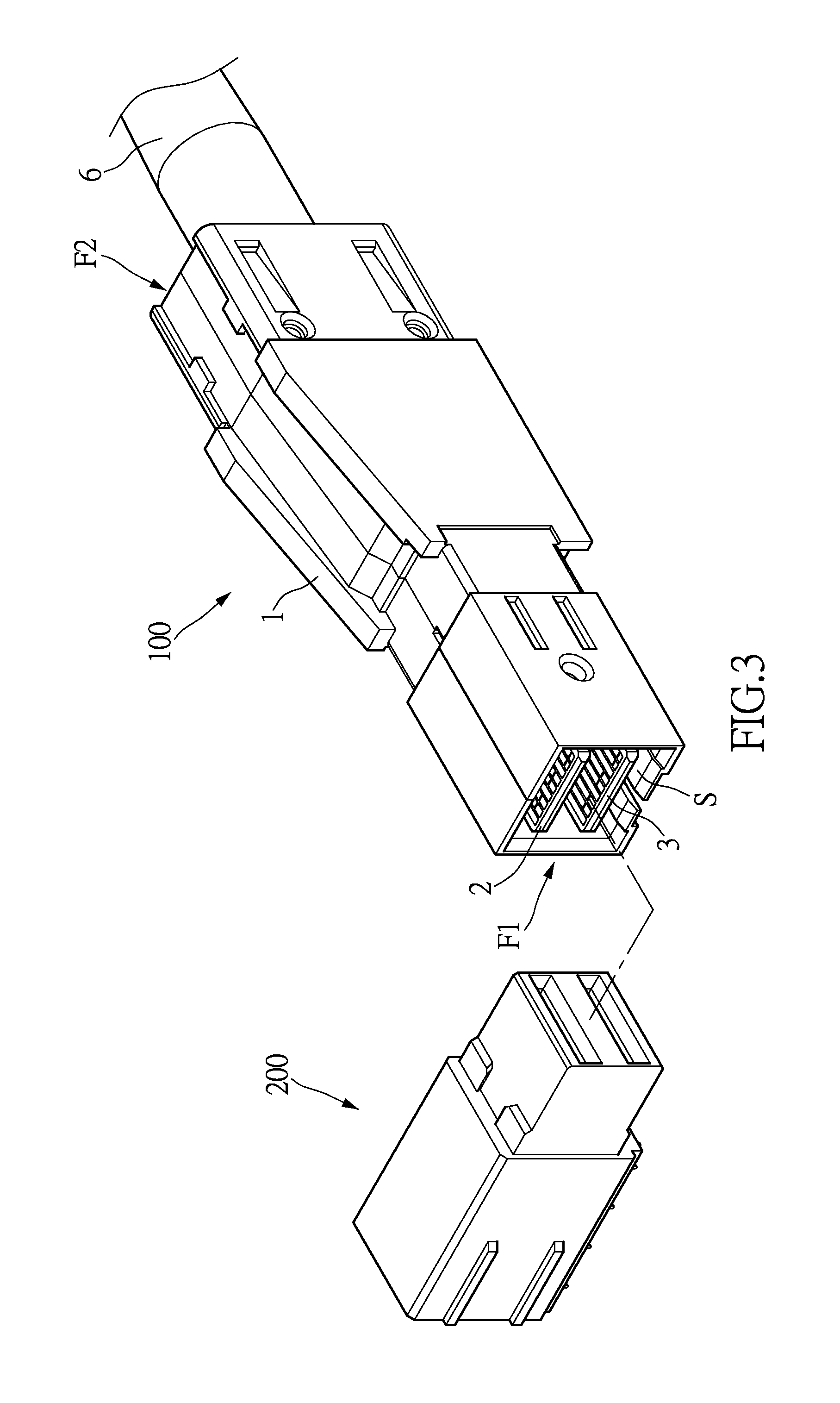
[0025]Referring to FIG. 3, the present disclosure provides an optical connector 100 for transmitting and receiving optical signals. The optical connector transmits data in a bi-directional manner with an output / input connector 200. The output / input connector 200 is installed on a main engine (not shown in the figure) such as but not limited to a server or an industrial computer having a need for transmitting / saving large amount of data. The optical connector 100 transmit and receive data at different speeds, including but limited to one gigabit per sec...


PUM


Abstract

The instant disclosure relates to bi-direction data transmission method, high-frequency connector and an optical connector using the same. The optical connector includes a first circuit board, a second circuit board, a high-frequency connector and an optical fiber cable. One optical engine is set on the first circuit board. The high-frequency connector is set between the first circuit board and the second circuit board for connecting both two circuit boards. The high-frequency connector includes an insulation base. The insulation base has at least one terminal-accommodating region. Pluralities of connection terminals are inserted into the terminal-accommodating regions of the insulation base. The optical fiber cable connects to the one optical engine.

Description

BACKGROUND OF THE INVENTION[0001]1. Field of the Invention[0002]The present disclosure relates to a high-frequency connector, an optical transceiver and a bi-directional data transmission method using the same; in particular, to an optical transceiver which transmits data through a combination of a high frequency connector an optoelectronic module, reducing the production cost and improving the production quality.[0003]2. Description of Related Art[0004]The term connector is a general reference to connecting units and accessories thereof for transferring electrical signals and power. As bridges for signals, connectors are essential to operation of electronic systems and their qualities dictate reliability of transmission of electric current and signals. Given the trend for faster and miniaturized electronic products, current connectors are mostly high speed interfaces such as mini SAS HD, PCI express, InfiniBand, SerialATA, Serial SCSI, DVI, HDMI, etc. Due to significant increase in...

Claims


Application Information

Patent Timeline
Patent Type & Authority Applications(United States)
IPC IPC(8): G02B6/42
CPCG02B6/4279G02B6/4246G02B6/428G02B6/4284
Inventor SU, HOU-ANCHAN, CHI-JUNGHSU, HUNG-WEI
Owner NEXTRONICS ENG CORP
Why Eureka
Try Eureka