Sound generator for an Anti-noise system for influencing exhaust noise and/or intake noise of a motor vehicle

Active Publication Date: 2015-01-22
PUREM GMBH
View PDF0 Cites 8 Cited by
  • Summary
  • Abstract
  • Description
  • Claims
  • Application Information

AI Technical Summary

Benefits of technology

The present invention provides a sound generator for an anti-noise system for vehicles that can withstand excessive displacement of the membrane. This is achieved through a membrane stop that prevents an excessive displacement of the membrane and thus of the voice coil by its at least one projection abutting against a portion of the membrane. The contact surfaces of the membrane stop's projections are dimensioned to distribute the force acting on the membrane over a large surface area, reducing the likelihood of damage to the membrane while avoiding adverse effects to air flowing between the loudspeaker basket and the membrane.

Problems solved by technology

These noises are often regarded as being disadvantageous.
Present-day engines with small displacement often cannot naturally generate such intended characteristic noise.
The disadvantage of both operating principles is that they require a comparatively large volume and create a comparatively high resistance to the combusted fuel-air mixture, resulting in a drop of the overall efficiency of the vehicle and in increased fuel consumption.
Sound waves also occur in intake systems of internal combustion engines, which may be regarded as annoying.
With the above arrangement, there is a risk of the membrane and / or the voice coil being subject to mechanical damage due to an excessive displacement of the membrane and the voice coil supported by the membrane.
Also, for example, a high ambient air pressure may result in a formation of negative pressure inside the sound generator at the side facing away from the bell mouth altering the oscillation characteristics of the membrane and biasing it towards the permanent magnet.
Finally, also a control signal used for operating the loudspeaker may cause an excessive displacement of the membrane, for example, when the control signal is not well enough adapted to the loudspeaker used, or when the control signal stimulates a self-resonance of the loudspeaker.

Method used


Image

  • Sound generator for an Anti-noise system for influencing exhaust noise and/or intake noise of a motor vehicle
  • Sound generator for an Anti-noise system for influencing exhaust noise and/or intake noise of a motor vehicle
  • Sound generator for an Anti-noise system for influencing exhaust noise and/or intake noise of a motor vehicle

Examples


Embodiment Construction

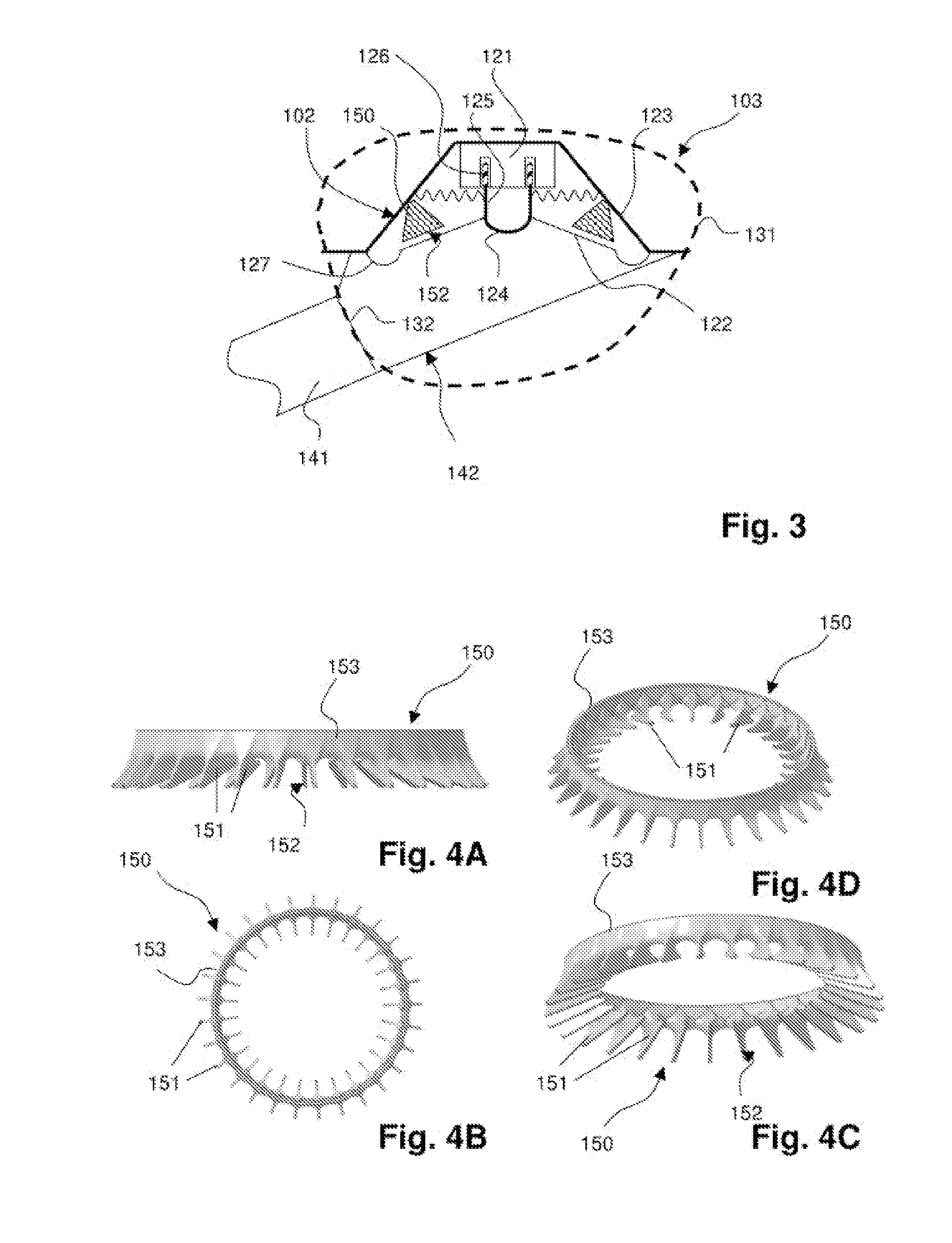
[0062]The schematic representation of FIG. 3 shows a cross-sectional view through the sound generator 103 according to an embodiment of the invention.

[0063]The sound generator 103 comprises an enclosure 131 housing, in its interior, a voice coil loudspeaker 102. The loudspeaker 102 comprises a permanent magnet 121 made of a neodymium-iron-boron alloy and a cone-like membrane 122 made of synthetic material. Both the permanent magnet 121 and the cone-like membrane 122 are supported by a loudspeaker basket 123 made from a steel sheet. The cone-like membrane 122 is hereby at its base area at its radial outside connected to the loudspeaker basket 133 via an elastic surround 127 made of synthetic material. The synthetic material can be elastic. The cone-like membrane 122 has rotational symmetry with an axial extent, from a base area (membrane base) to a top face (membrane top), and with a base area radial dimension that is larger than a top area radial dimension. The top face of the cone-...


PUM


Abstract

A sound generator 103 for an anti-noise system for influencing sound waves propagating in exhaust systems or intake systems of vehicles driven by an internal combustion engine includes a loudspeaker basket 123, a membrane 122 supported by the loudspeaker basket 123, a permanent magnet 121 supported by the loudspeaker basket 123, a voice coil 126 supported by a voice coil carrier 125 and a membrane stop 150. The voice coil 126 is located within a constant magnetic field generated by the permanent magnet 121. The voice coil carrier 125 is supported by the membrane 122. The membrane stop 150 is located on the loudspeaker basket 123 adjacent to the membrane 122. The membrane stop 150 includes a projection 151 extending towards the membrane 122. An anti-noise system using the sound generator and a vehicle using the anti-noise system are also provided.

Description

CROSS REFERENCE TO RELATED APPLICATIONS[0001]This present application claims priority of Patent Application DE 10 2013 011 937.5, filed Jul. 17, 2013 in Germany, the entire contents of which are incorporated by reference herein.FIELD OF THE INVENTION[0002]The present invention concerns a sound generator for an anti-noise system for influencing sound propagating through exhaust systems of vehicles driven by internal combustion engines (exhaust noise), and / or for influencing sound propagating through intake systems of internal combustion engines (intake noise).BACKGROUND OF THE INVENTION[0003]Regardless of the type of internal combustion engine (for example reciprocating piston engine, pistonless rotary engine or free-piston engine), noises are generated as a result of the successively executed strokes (in particular intake and compression of the fuel-air mixture, combustion and discharge of the combusted fuel-air mixture). On the one hand, the noises propagate through the internal co...

Claims


Application Information

Patent Timeline
IPC IPC(8): H04R1/00F01N1/06
CPCF01N1/065H04R1/00G10K9/18F02M35/125G10K11/1788G10K2210/3212G10K11/1785G10K11/17857G10K11/17883
Inventor PEITZ, MAXIMILIANDAVID, STEFFEN
Owner PUREM GMBH
Why Eureka
Try Eureka