Data processing apparatus, radar apparatus, and data processing method

a data processing apparatus and radar technology, applied in the field of radar equipment, can solve the problems of enlargement in two directions, difficult to change the magnification factor, small display of small yachts and boats that are relatively near, etc., and achieve the effect of easy setting the change of the magnification factor

Active Publication Date: 2015-01-22
FURUNO ELECTRIC CO LTD
View PDF1 Cites 2 Cited by
  • Summary
  • Abstract
  • Description
  • Claims
  • Application Information

AI Technical Summary

Benefits of technology

[0012]According to this data processing method, since in the digital filter processing, the range of the peripheral data used for the digital filter processing according to the distance from the antenna to the data of interest is changed, the range of the peripheral data that affect the value of the data of interest changes according to the distance. With this, widening the range of the peripheral data in the digital filter processing so that the data of interest is more easily affected by the peripheral data or, conversely, narrowing the range of the peripheral data so that the data of interest is less easily affected by the peripheral data is possible. By changing the size of the influence of the peripheral data, the magnification factor of the images by the digital filter processing can be changed according to the distance from the antenna.
[0013]According to the present invention, magnification can be done according to the distance from the antenna, and setting the change of the magnification factor becomes easy.

Problems solved by technology

In this way, in a radar apparatus that is mounted on a ship, when the antenna rotates and changes the azimuth to and from which radio waves are transmitted and received to capture objects in the periphery, since the beam width has an angle, when trying to display a ship that is sailing at a relative distance with an appropriate resolution, the display of small yachts and boats that are relatively near becomes small and difficult to see.
However, since the procedure for enlargement in the two-dimensional direction is complex, changing the magnification factor is relatively difficult.

Method used


Image

  • Data processing apparatus, radar apparatus, and data processing method
  • Data processing apparatus, radar apparatus, and data processing method
  • Data processing apparatus, radar apparatus, and data processing method

Examples


first embodiment

Configuration of the Radar Apparatus

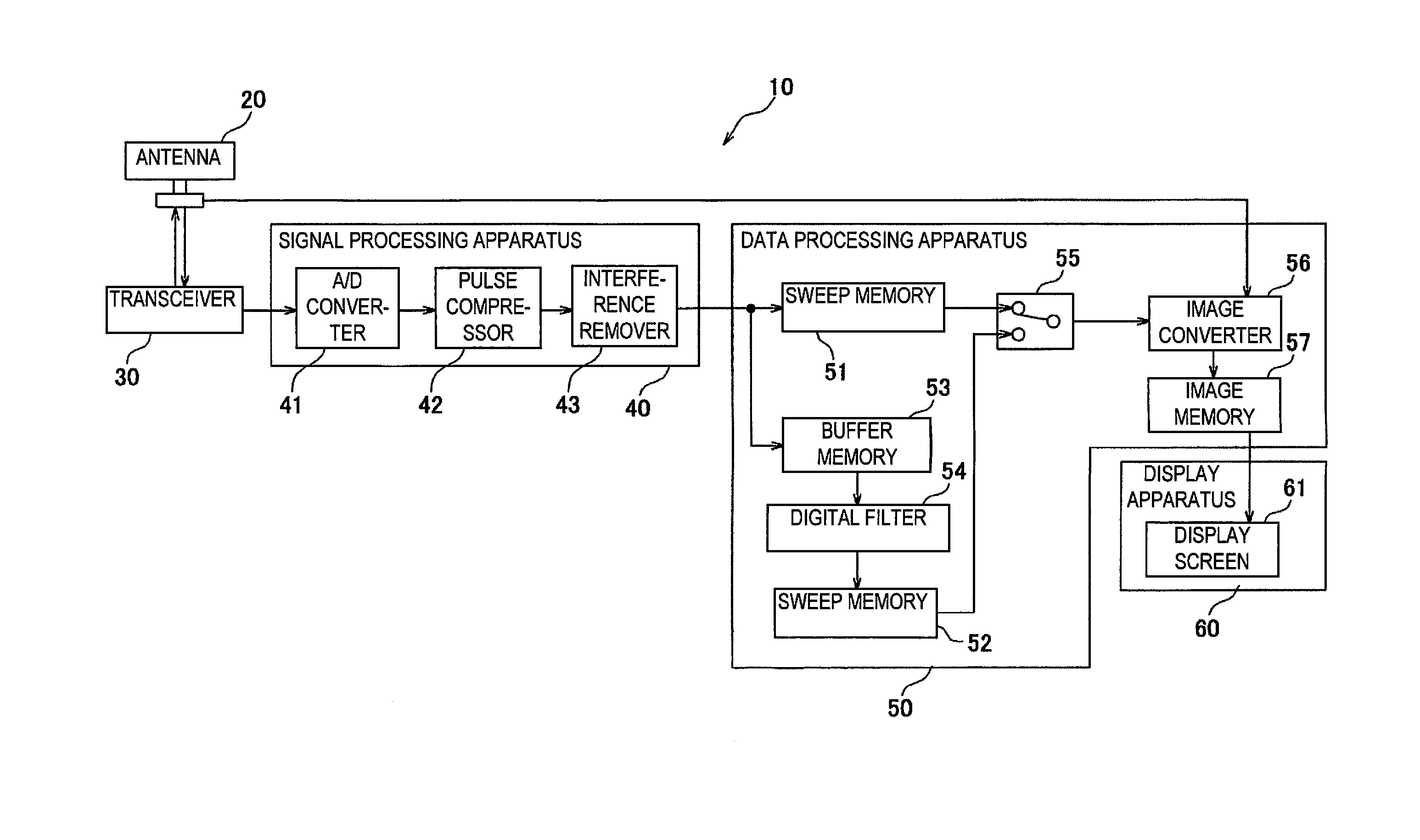
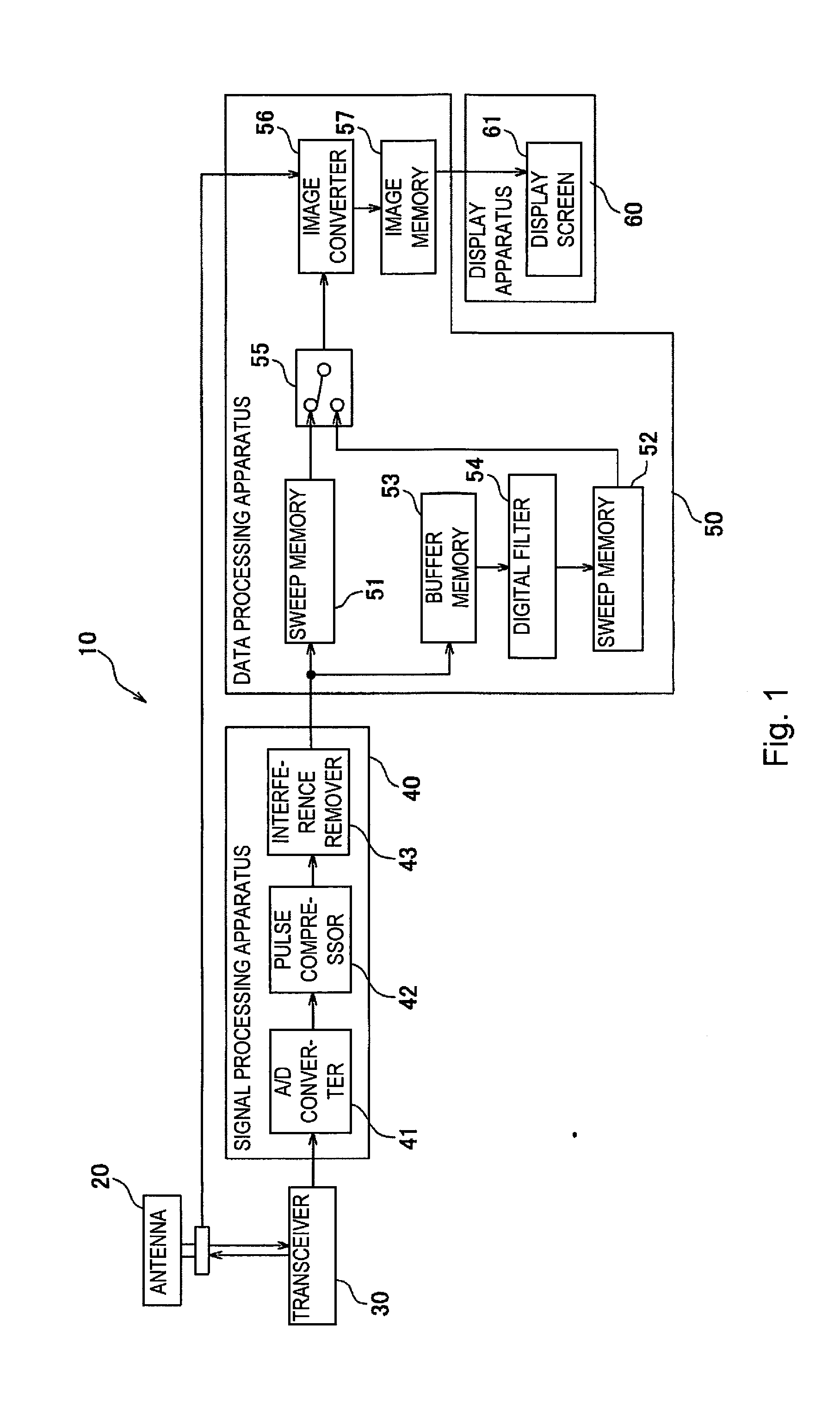
[0025]The radar apparatus according to the first embodiment of the present invention will be explained below using the drawings. FIG. 1 is a block diagram showing a schematic configuration of this radar apparatus. The radar apparatus 10 shown in FIG. 1 comprises an antenna 20, a transceiver 30, a signal processing apparatus 40, a data processing apparatus 50, and a display apparatus 60. Additionally, the data processing apparatus 50 comprises sweep memories 51 and 52, a buffer memory 53, a digital filter 54, a selector 55, an image converter 56, and an image memory 57.

[0026]In FIG. 1, the configuration in which the selector 55 is selecting the sweep memory 51, that is, a configuration comprising the antenna 20, the transceiver 30, the signal processing apparatus 40, the sweep memory 51, the selector 55, the image converter 56, image memory 57, and the display apparatus 60, is the same configuration as that in a conventional radar apparatus. Also, ...

second embodiment

[0060]Next, a radar apparatus according to the second embodiment of the present invention will be explained using FIG. 8. The radar apparatus 10A according to the second embodiment comprises an antenna 20, a transceiver 30, a signal processing apparatus 40, a data processing apparatus 50A, and a display apparatus 60 in the same way as the radar apparatus 10 according to the first embodiment.

[0061]The point in which the first embodiment and the second embodiment are different is in the difference in the configuration of the data processing apparatuses 50 and 50A. Since the configuration and the behavior of the antenna 20, the transceiver 30, the signal processing apparatus 40, and the display apparatus 60 are the same for the radar apparatus 10 of the first embodiment and the radar apparatus 10A of the second embodiment, the explanations for these have been omitted.

[0062]In the above-described first embodiment, a case is shown in which the digital filter 54 processes the sweep data, ...

modified example 1

[0070]In the above-described first embodiment and second embodiment, a digital filter 54 that is a maximum value filter was used as the FIR filter. However, the FIR filter can be a filter besides a maximum value filter; for example, this filter can be a moving average filter that replaces the values of the data of interest with the average value of the peripheral data that are in the periphery of the data of interest.

[0071]A moving average filter is used in place of a digital filter 54 and is set so that the filter processing is changed by conducting a change that increases at least one of either the data numbers in the distance direction or the data numbers in the azimuth direction of the peripheral data corresponding to those that are closer in distance to the antenna 20 than a prescribed distance than the data numbers in the distance direction and the data numbers in the azimuth direction of the peripheral data of the data of interest that correspond to those that are farther.

[00...


PUM


Abstract

A data processing apparatus that can set the magnification factor according to the distance from the antenna is provided so that the display of objects close to the antenna is easier to see and with which the changes in the settings of the magnification factor is easy. The buffer memory stores the digital signals converted by the A/D converter in association with the distance and azimuth with respect to the antenna. The digital filter filters the digital signals read from the buffer memory. A digital filter is provided that converts a value of data of interest, of digital data stored in the memory, to a value based on values of the data of interest to be processed and peripheral data in a periphery of the data of interest, and the digital filter changes a range of the peripheral data used for a filter processing according to the distance from the antenna to the data of interest.

Description

CROSS REFERENCE TO RELATED APPLICATIONS[0001]This application is a U.S. National stage of International Application No. PCT / JP2013 / 053887 filed on Feb. 18, 2013. This application claims priority to Japanese Patent Application No. 2012-052812 filed on Mar. 9, 2012. The entire disclosure of Japanese Patent Application No. 2012-052812 is hereby incorporated herein by reference.BACKGROUND[0002]1. Field of the Invention[0003]The present invention relates to a radar apparatus that displays objects around an antenna captured by radio waves that are transmitted and received by the antenna, along with a data processing apparatus and a data processing method used with the radar apparatus.[0004]2. Background Information[0005]In a radar apparatus, in general, an object (ships at sea, buoys, terrain and structures on land, etc.) is detected by capturing the reflected radio waves that are emitted, and the detected object is displayed on a display. For this reason, the antenna transmits a beam of ...

Claims


Application Information

Patent Timeline
Patent Type & Authority Applications(United States)
IPC IPC(8): G01S7/04G01S7/02G01S13/89G01S13/937
CPCG01S7/02G01S7/04G01S13/89G01S7/295G01S7/064G01S7/12G01S13/9307G01S13/426G01S13/282G01S13/937
Inventor NISHIYAMA, KOJI
Owner FURUNO ELECTRIC CO LTD
Why Eureka
Try Eureka