Mirror drive device and driving method thereof
- Summary
- Abstract
- Description
- Claims
- Application Information
AI Technical Summary
Benefits of technology
Problems solved by technology
Method used
Image
Examples
first embodiment
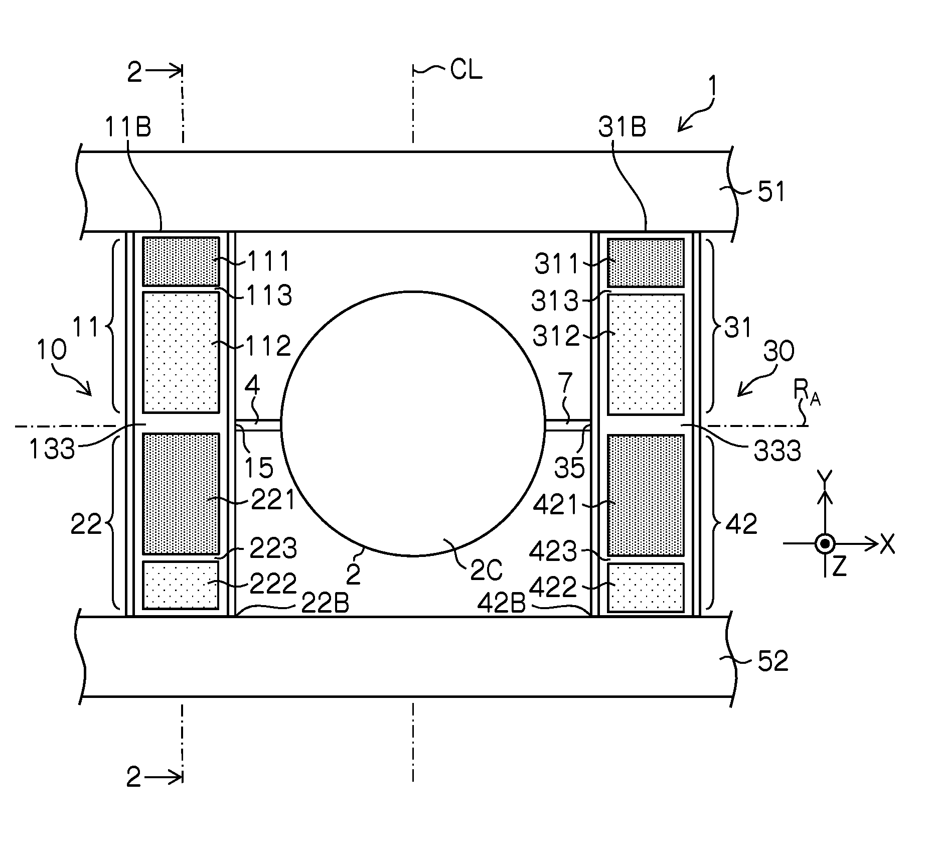
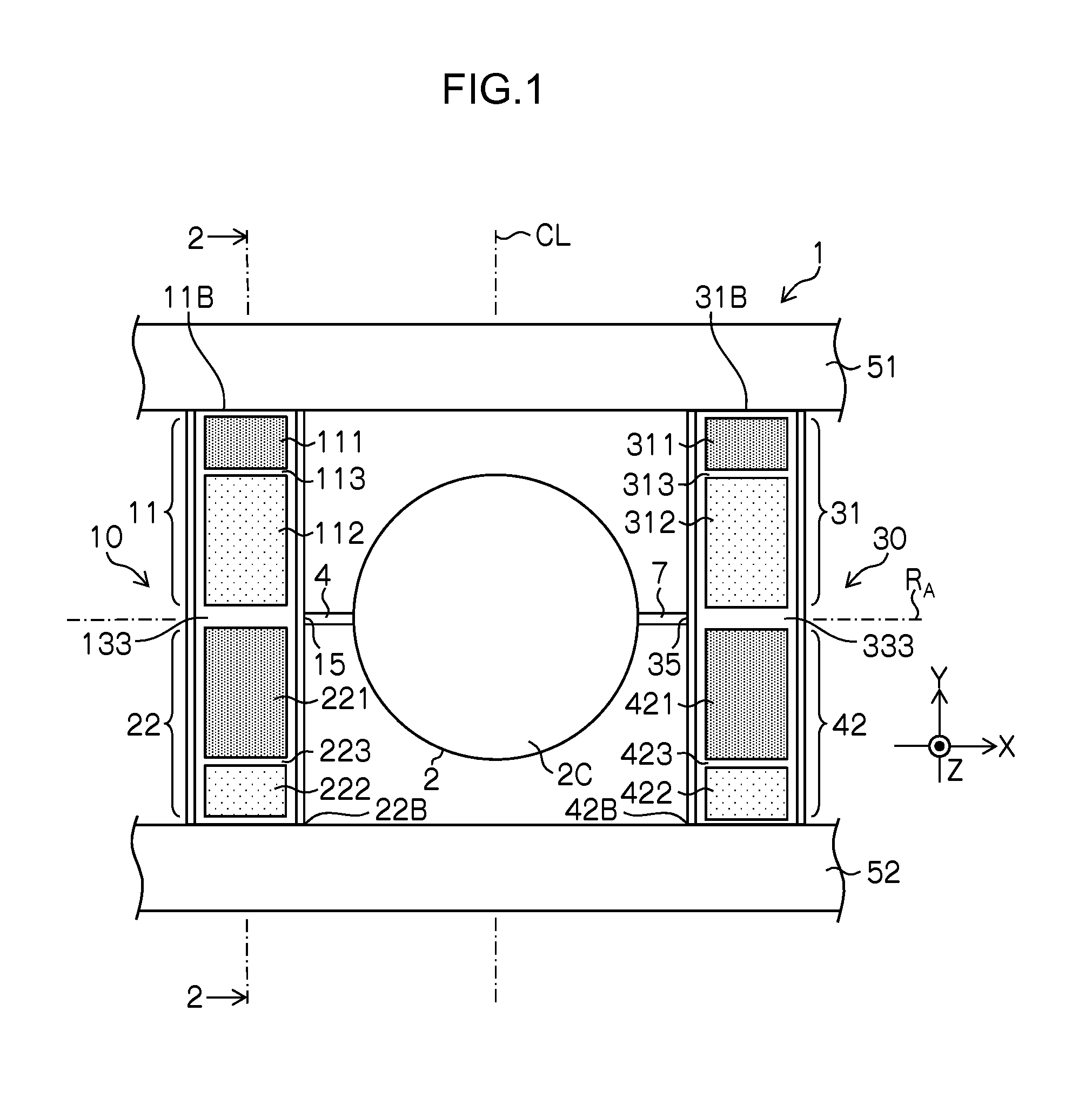
[0071]FIG. 1 is a plan view of a structure of a micro scanner device according to a first embodiment. In this example, a micro scanner device 1 that corresponds to “mirror drive device” includes a mirror section 2 having a circular shape, a first torsion bar section 4 and a second torsion bar section 7 that support the mirror section 2 from both sides of the diameter direction, a first actuator section 11 and a second actuator section 22 that are connected to the first torsion bar section 4 and operate as a piezoelectric actuator section 10, a third actuator section 31 and a fourth actuator section 42 that are connected to a second torsion bar section 7 and operate as a piezoelectric actuator section 30.
[0072]The first actuator section 11 and the second actuator section 22 are connected to each other through a coupling section 15, and the first torsion bar section 4 is connected to the coupling section 15. Similarly, the third actuator section 31 and the fourth actuator section 42 a...
utility example 1
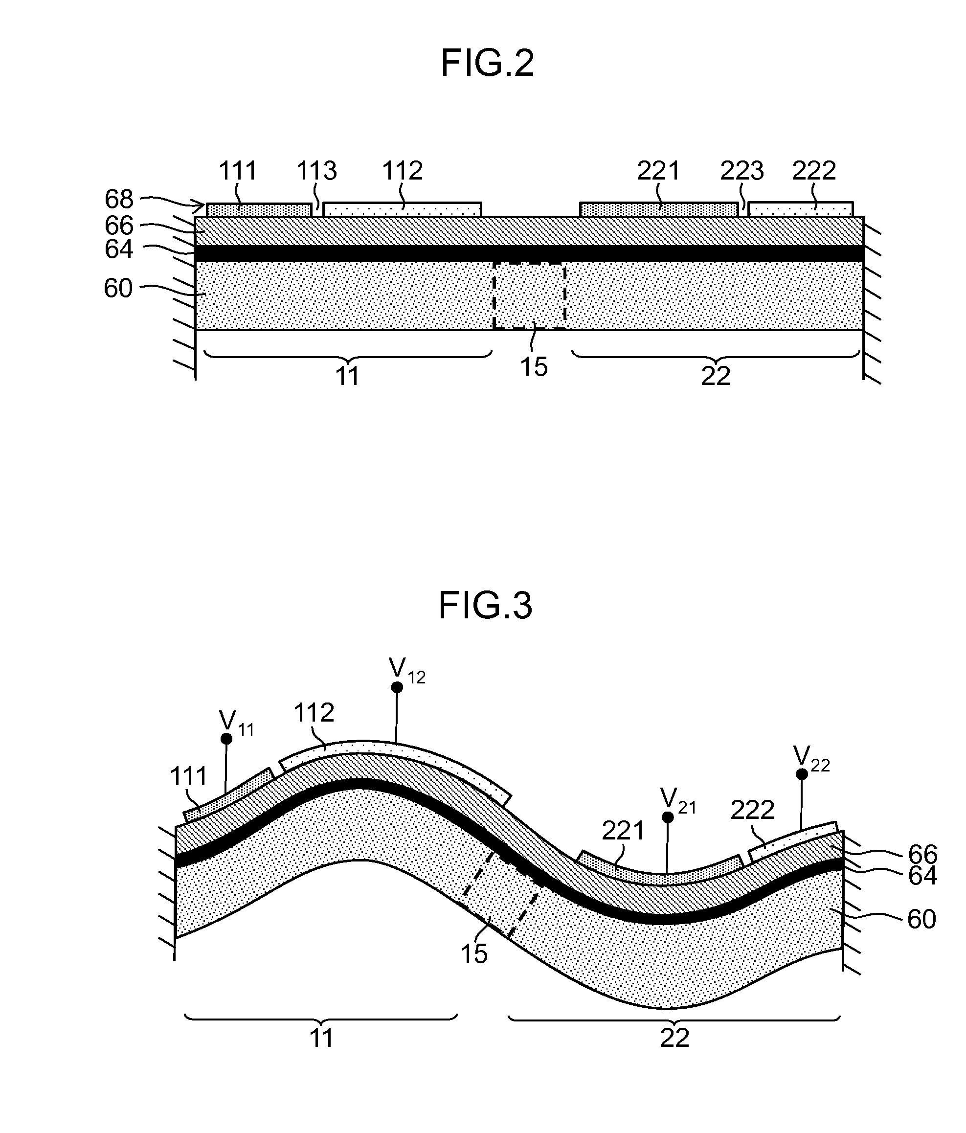
[0115]FIG. 7 is a diagram illustrating an example in which all of the first electrode section 111 to the eighth electrode section 422 are used as driving electrodes. A portion in which the piezoelectric body 66 lies between each of the electrode sections (111, 112, 221, 222, 311, 312, 421, and 422) as the upper electrode 68 and the lower electrode 64 (see FIG. 2) operates as a piezoelectric element section. In this example, all of the electrode sections are used as driving electrodes, and all of the piezoelectric element sections function as driving force generation sections.
[0116]In this case, as illustrated in FIG. 7, the same drive voltage V2 is applied to the electrode group of the first electrode section 111 of the first actuator section 11, the third electrode section 221 of the second actuator section 22, the fifth electrode section 311 of the third actuator section 31, and the seventh electrode section 421 of the fourth actuator section 42, and the drive voltage V1 that has ...
utility example 2
[0120]FIG. 8 is a diagram illustrating an example in which a part of the first electrode section 111 to the eighth electrode section 422 is used as a sensing (detection) electrode for stress detection. Here, an example is described in which the fourth electrode section 222 and the eighth electrode section 422 are used as detection electrodes, and the other electrode sections are used as driving electrodes.
[0121]The detection electrode is set at a floating potential and detects voltage that is generated by a piezoelectric effect of the piezoelectric body 66 (positive piezoelectric effect). In FIG. 8, electrodes represented by “s” are detection electrodes that are used to detect a sensing signal and are set at a floating potential.
[0122]As described above, when a part of the plurality of electrodes sections is used as a voltage detection section, voltage that is generated by the positive voltage effect of the piezoelectric body can be detected, and a stress of the actuator section can...
PUM
 Abstract
Description
Claims
Application Information
 - R&D
- Intellectual Property
- Life Sciences
- Materials
- Tech Scout
- Unparalleled Data Quality
- Higher Quality Content
- 60% Fewer Hallucinations
Browse by: Latest US Patents, China's latest patents, Technical Efficacy Thesaurus, Application Domain, Technology Topic, Popular Technical Reports.
© 2025 PatSnap. All rights reserved.Legal|Privacy policy|Modern Slavery Act Transparency Statement|Sitemap|About US| Contact US: help@patsnap.com


