Organic electroluminescent panel and vehicle lamp

Inactive Publication Date: 2015-01-22
KOITO MFG CO LTD
View PDF3 Cites 17 Cited by
  • Summary
  • Abstract
  • Description
  • Claims
  • Application Information

AI Technical Summary

Benefits of technology

The present invention provides an organic electroluminescent panel that can achieve improved luminous intensity with a narrow light emitting portion. This is achieved by arranging the organic light emitting layer close to the metal electrode to suppress brightness degradation due to voltage drop of the transparent conductive film. Additionally, a micro-reflective metal layer between the transparent conductive film and the organic light emitting layer enhances the brightness of the light emitting portion. The invention also provides a vehicle lamp with a feeling of depth with thin configuration by using two organic electroluminescent panels with overlapping light emitting portions.

Problems solved by technology

When using an organic electroluminescent panel in a vehicle lamp, it is sometimes difficult to provide sufficient luminous intensity required for the vehicle lamp.
However, organic electroluminescent devices have relatively low brightness.
Therefore, it is difficult to satisfy the minimum luminous intensity of 4 candela with an organic electroluminescent panel having a narrow light emitting portion.

Method used


Image

  • Organic electroluminescent panel and vehicle lamp
  • Organic electroluminescent panel and vehicle lamp
  • Organic electroluminescent panel and vehicle lamp

Examples


Embodiment Construction

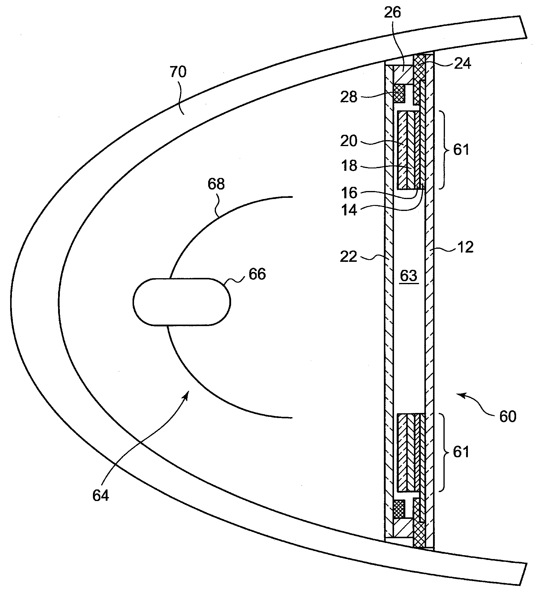
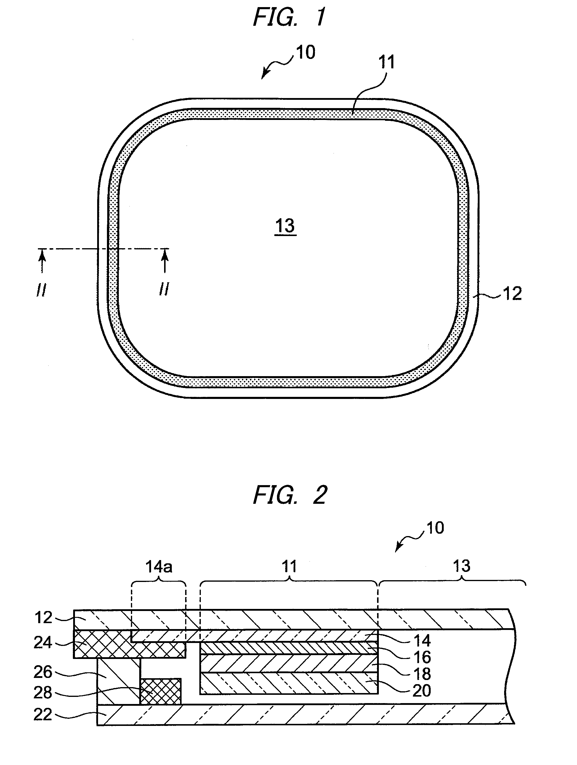
[0020]FIG. 1 is a schematic plan view of an organic electroluminescent panel 10 according to one or more embodiments of the present invention. The organic electroluminescent panel 10 is configured such that a light emitting portion 11 is provided between two glass substrates, each having a substantially rectangular shape. In the illustrated example, the light emitting portion 11 is situated along a peripheral edge of the glass substrates in an annular form. A region on an inner side of the light emitting portion 11 is configured as a transparent region 13 that allows light to pass through.

[0021]FIG. 2 is a sectional view of the organic electroluminescent panel 10 taken along the line II-II shown in FIG. 1. The organic electroluminescent panel 10 has a structure in which a transparent conductive film 14 (e.g., indium tin oxide (ITO)), a micro-reflective metal layer 16, an organic light emitting layer 18, and a cathode layer 20 (a transparent conductive film on the back surface side) ...


PUM


Abstract

An organic electroluminescent panel is provided. The organic electroluminescent panel includes a substrate made of glass or transparent resin, a light emitting portion provided along a peripheral edge of the substrate, and a metal electrode. The light emitting portion comprises a cathode layer, a transparent conductive film having an extension portion, the extension portion extending toward an outer peripheral portion of the substrate and contacting the metal electrode, and an organic light emitting layer provided between the cathode layer and the transparent conductive film. The metal electrode is provided on the outer peripheral portion of the substrate to serve as an anode.

Description

CROSS-REFERENCE TO RELATED APPLICATION[0001]The present application claims priority from Japanese Patent Application No. 2013-150687 filed on Jul. 19, 2013, the entire content of which is incorporated herein by reference.BACKGROUND OF INVENTION[0002]1. Field of the Invention[0003]The present invention relates to an organic electroluminescent panel and a vehicle lamp having the organic electroluminescent panel.[0004]2. Related Art[0005]A related art vehicle lamp has an organic electroluminescent device as a light source. For example, a related art vehicle lamp has a main light source and a sub light source arranged inside a lamp chamber provided between a housing and a transparent cover. The sub light source has a planar light emitting device configured as an organic electroluminescent device. The planar light emitting device is provided to surround the main light source (see, e.g., JP 2011-150888 A).[0006]When using an organic electroluminescent panel in a vehicle lamp, it is someti...

Claims


Application Information

Patent Timeline
IPC IPC(8): F21S8/10H01L51/52
CPCH01L51/5215H01L51/5209H01L51/5246F21S48/2212H01L51/5259F21S48/215H01L51/5271B60Q1/0041B60Q1/0052B60Q1/2607F21S48/1154F21S48/212F21S48/217F21Y2103/022F21Y2103/025F21Y2105/008F21Y2111/008H01L25/048H01L51/5212H01L51/5265H01L2251/5361H01L2924/0002B60Q1/0058F21S43/195F21S43/14F21S43/145F21S43/26H10K59/90H10K50/813H10K50/814H10K50/846H10K50/852H01L2924/00H10K50/816H10K50/856H10K50/8426
Inventor SHIDO, MASAYAITO, TORU
Owner KOITO MFG CO LTD
Why Eureka
Try Eureka