
Stereo x-ray tube based suppression of outside body high contrast objects

a technology of x-ray tube and object, applied in the field of image processing apparatus, can solve the problems of disturbing visual content, spurious image content, image content originating from instruments or other devices outside the body, etc., and achieve the effect of saving cpu tim

Active Publication Date: 2015-01-22
KONINKLJIJKE PHILIPS NV
View PDF0 Cites 1 Cited by
  • Summary
  • Abstract
  • Description
  • Claims
  • Application Information

AI Technical Summary

Benefits of technology

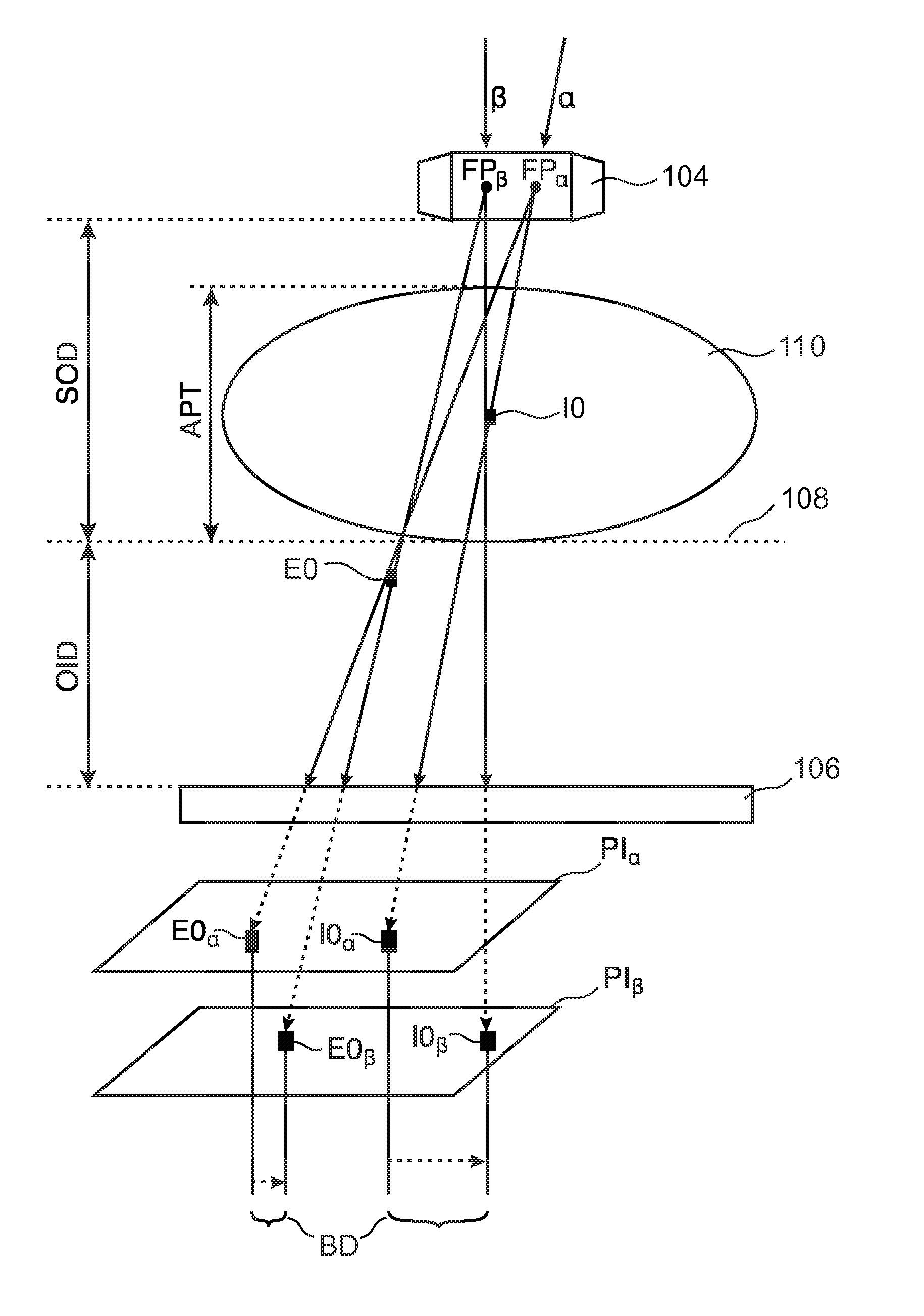
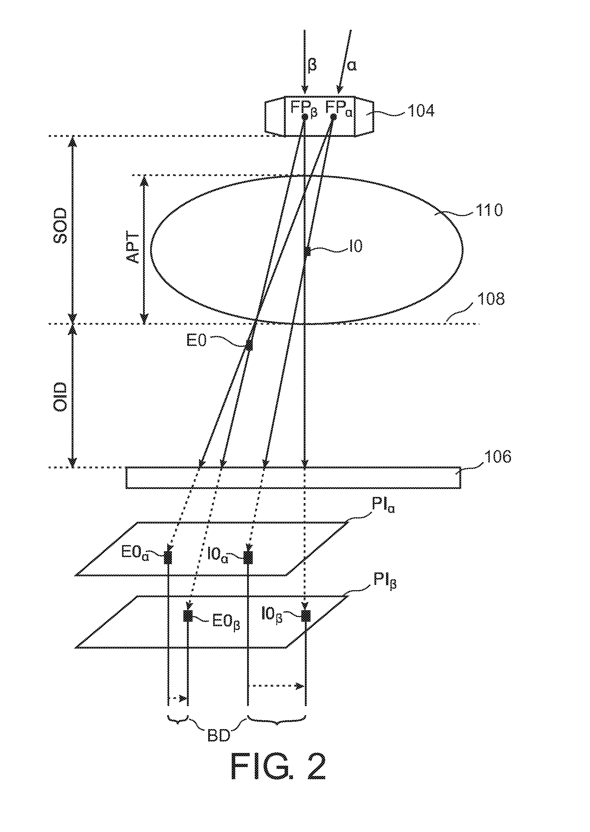
The apparatus described in this patent uses the opportunity of stereo or binocular disparity in image content to estimate the depth of structures within the body. By removing image content from objects outside the body, a clear view of clinically important structures can be achieved. Additionally, if the object is determined to be external based on image depth, the object footprint detector can bypass the image depth resolver, saving CPU time. This results in faster and more accurate object recognition.

Problems solved by technology

In interventional imaging settings, cables, electronic devices and sundry equipment are often located outside a patient's body and frequently create spurious image content in intra-interventional imaging.
This image content originating from instrumentation or other devices outside the body can be visually disturbing, in particular in time-critical settings.

Method used


Image

  • Stereo x-ray tube based suppression of outside body high contrast objects
  • Stereo x-ray tube based suppression of outside body high contrast objects
  • Stereo x-ray tube based suppression of outside body high contrast objects

Examples


Embodiment Construction

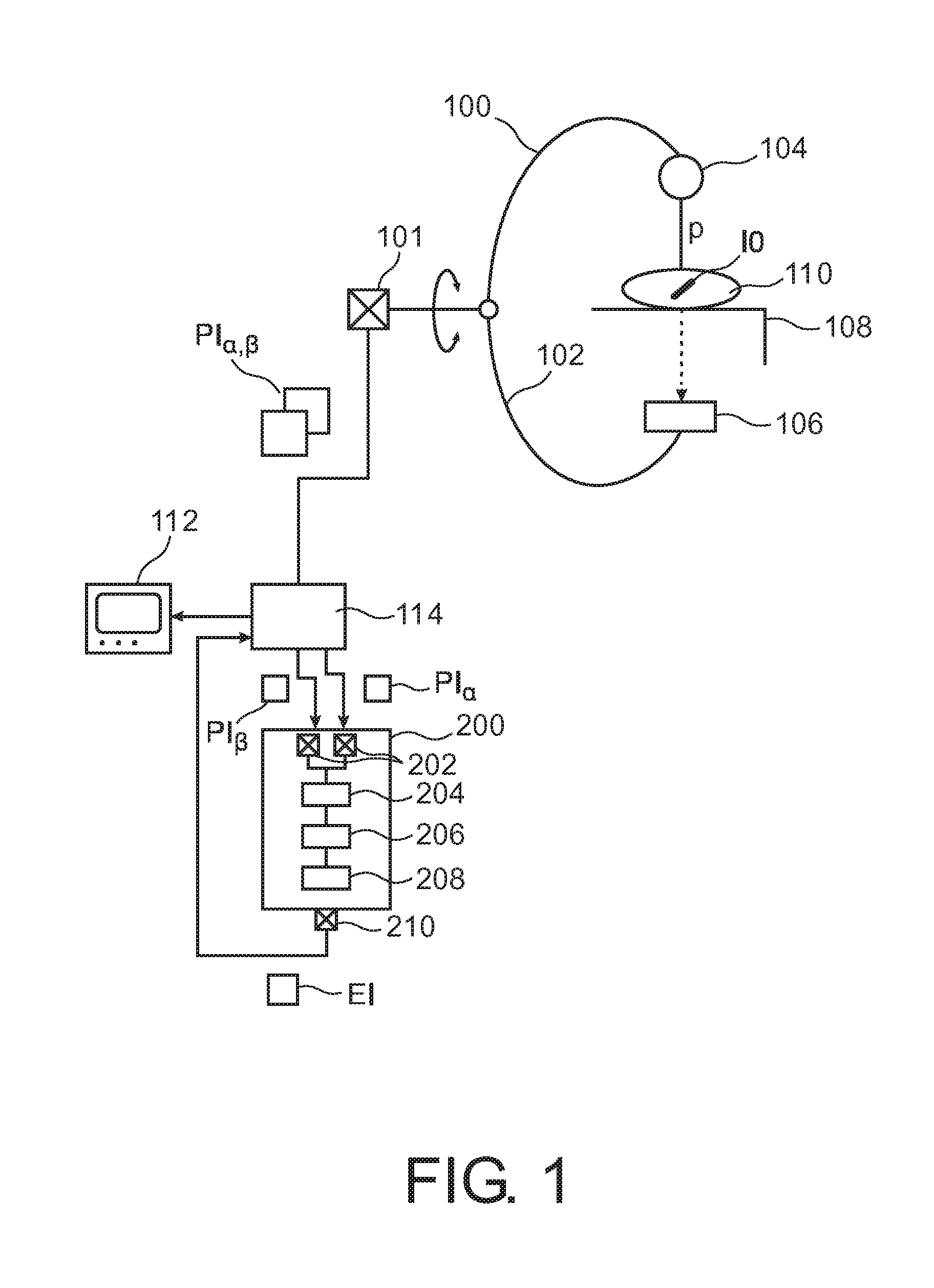
[0031]With reference to FIG. 1, there is shown an x-ray imager 100 of the C-arm type. X-ray imager 100 is used to acquire at least two projection images PIα, PIβ of a patient 110 who is supported by an examination table 108.

[0032]Imager 100 comprises a rigid C-arm structure 102 journaled on a bearing. Journaling allows rotation of C-arm 102 around a first axis passing through journaling.

[0033]C-arm structure 102 can thus be positioned at various rotation angles a around patient 110.

[0034]C-arm 102 carries at one of its ends an x-ray source 104 and at the other end a detector 106 in opposed spatial relationship to x-ray source 104. Detector 106 includes an array of detector cells (not shown).

[0035]X-rays are emitted from x-ray source 104. The X-rays pass through patient's body 110 and are then detected at detector 120. The X-rays are formed from as an X-ray pencil beam p.

[0036]Each x-ray beam p is attenuated as it passes through the patient and impact on same. It is this attenuated x...


PUM


Abstract

A double focal spot X-ray tube (104) is used to acquire a set of two images PIα, PIβ for a given gantry position from slightly different view positions. The stereo or binocular disparity (BD) of imaged structures is used to estimate the object depth in view direction, which in turn is used to discriminate between objects inside IO and outside EO the body. Respective structures are virtually removed from the images PIα, PIβ.

Description

FIELD OF THE INVENTION[0001]The present invention relates to an image processing apparatus, to a method of image processing, to an imaging system, to a computer program element, and to a computer readable medium.BACKGROUND OF THE INVENTION[0002]In interventional imaging settings, cables, electronic devices and sundry equipment are often located outside a patient's body and frequently create spurious image content in intra-interventional imaging. This image content originating from instrumentation or other devices outside the body can be visually disturbing, in particular in time-critical settings.SUMMARY OF THE INVENTION[0003]There may therefore be a need for an image processing apparatus to support a clinician during imaging.[0004]The object of the present invention is solved by the subject matter of the independent claims wherein further embodiments are incorporated in the dependent claims.[0005]It should be noted that the following described aspects of the invention equally apply...

Claims


Application Information

Patent Timeline
Patent Type & Authority Applications(United States)
IPC IPC(8): A61B6/00G06T15/00G06T5/00
CPCA61B6/5252A61B6/5258A61B6/4441G06T2207/20172G06T15/00G06T5/00G06T2207/10116A61B6/4021A61B6/03A61B6/5235G06T2207/30004G06T7/0075G06T7/593
Inventor LORENZ, CRISTIANGRASS, MICHAELSCHAFER, DIRKBRENDEL, BERNHARD JOHANNES
Owner KONINKLJIJKE PHILIPS NV
Learn More