Layer heat exchanger for high temperatures

a heat exchanger and high temperature technology, applied in indirect heat exchangers, laminated elements, lighting and heating apparatus, etc., can solve the problems of thermal mechanical heat exchanger structure, outward tightness of heat exchanger, and tightness of layer blocks in the interior, so as to achieve sufficient internal tightness

Inactive Publication Date: 2015-01-29
BEHR GMBH & CO KG
View PDF5 Cites 2 Cited by
  • Summary
  • Abstract
  • Description
  • Claims
  • Application Information

AI Technical Summary

Benefits of technology

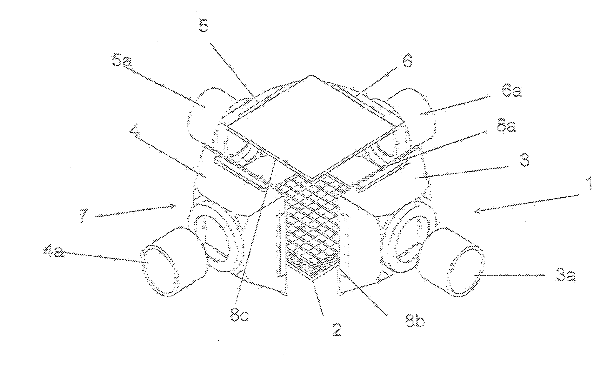
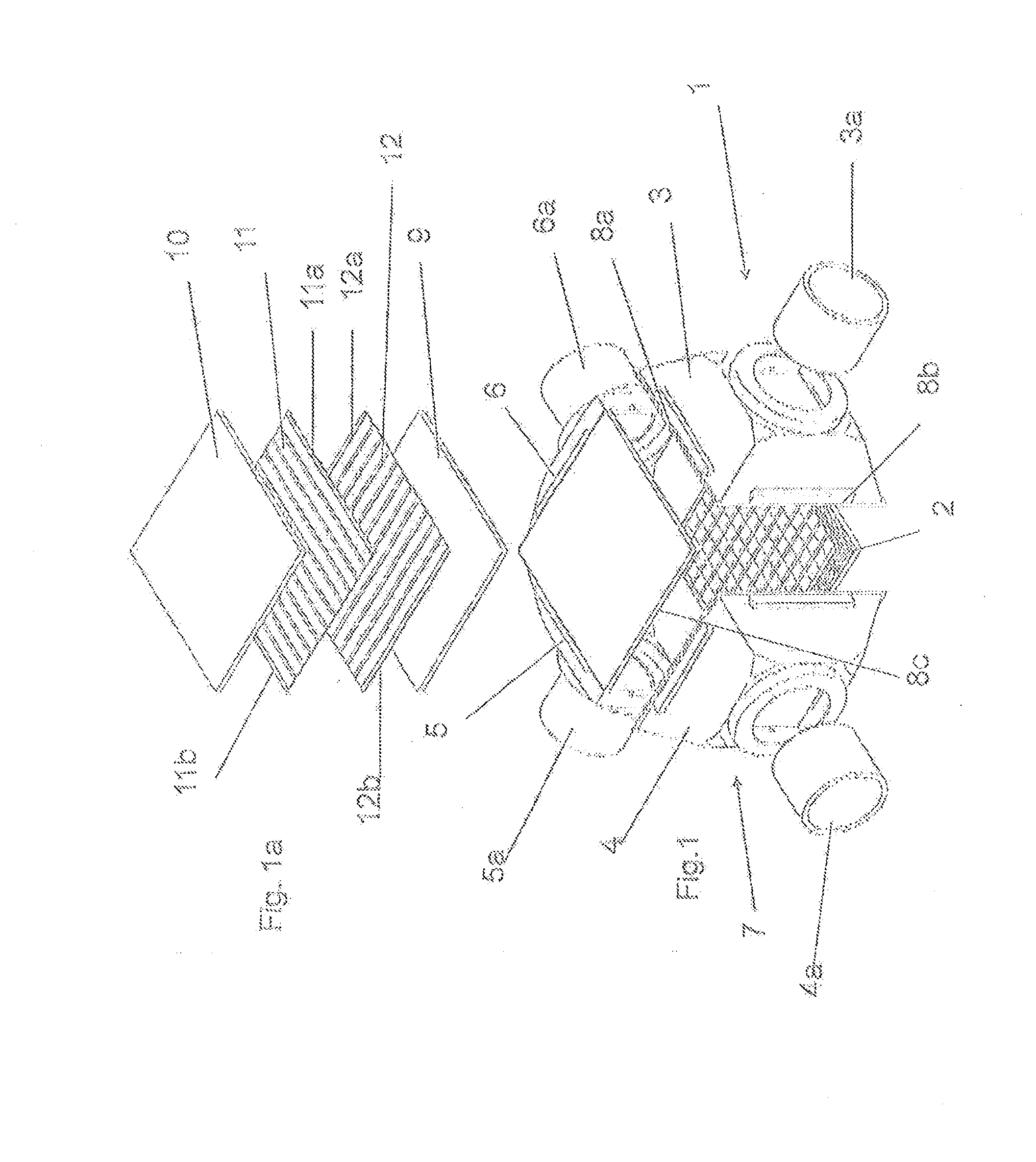
[0010]According to the invention, the layer heat exchanger is characterized by a housing with a high heat resistance and stiffness, as well as a layer block with a soft and tough core relative to the housing. Compared with the layer block, the housing thereby forms a relatively stiff counter support, which based on its novel design is capable, particularly at high temperatures, of absorbing thermally induced expansion forces originating from the layer block. Based on this firm counter support, the soft and tough core of the layer block will deform elastically or also plastically in part, which is taken into account. It turned out surprisingly that the internal leakage of the layer heat exchanger of the invention is much lower than in the aforementioned prior art layer heat exchangers. The internal leakage arises during operation, e.g., during use of the heat exchanger in the periphery of a high-temperature fuel cell because gas that has a temperature of 900 to 950° C. encounters the cold layer block during a cold start. The thin layer plates heat more rapidly than the thicker housing material, so that because of the thus predefined thermal expansion c of the plates, according to Hook's law, a force F˜E·ε (E=elasticity modulus) on the housing arises. When the housing of the invention opposes the force exerted by the plates with a sufficiently high heat resistance, the layer plates in the interior (of the layer block) are more likely to deform elastically or plastically and thereby to reduce the force. It is accepted in this case that the layer plates in the interior may be damaged with often repetition of the cold start; i.e., a relative internal leakage is permitted according to the invention. It is advantageous that the damage is limited locally, namely, to regions that reach the highest temperatures. This limits the internal leakage. The extent to which an internal leakage forms during operation depends on the selection of the materials, particularly the material of the layer plate. The external tightness is absolutely assured, however; i.e., the escape to the outside of gas that has a temperature of 950° C. and may also contain hydrogen is prevented in each case.
[0014]According to another embodiment, the cover and layer plates are made of a material that has a lower heat resistance compared with the material of the housing, particularly a low hot yield strength σ0.2. By means of this pairing of materials with a different heat resistance for the housing, on the one hand, and the layer block, on the other, the aforementioned expansion behavior of the layer block is achieved at high temperature stresses; i.e., a sufficient internal tightness and a complete external tightness are assured.
[0020]According to an embodiment, the wall thickness of the housing is about 1.5 mm and that of the layer plates about 0.3 mm. The wall thickness of the housing material, in contrast to the wall thickness of the layer and cover plate material, can be relatively low, when the heat resistance of the housing material is high relative to the heat resistances of the layer plate material. It is especially preferable accordingly when the housing material consists of a high-temperature-resistant material with a low thickness such as, for example, 2.4856 with a 1.0 mm or 0.5 mm wall thickness and the layer and / or cover plate material of a soft material such as the aforementioned FeCrAl alloys. The especially minor difference in mass between the housing, on the one hand, and the layer and cover plates, on the other, leads to especially low thermal stresses. An Al content of ≧2%, especially preferably ≧3% is especially useful in this case.
[0021]According to another embodiment, it is provided alternatively or cumulatively that the layer and cover plates are connected to one another by bonding only on the front side at their sealing edges, preferably by soldering or welding. Ribs or nubs, which are located in the interior of the heat exchanger or lead from the outside into the interior of the heat exchanger, should thereby not be connected to one another by bonding or at least to the lowest extent possible. The advantage is achieved thereby that the layer block is securely sealed toward the outside and remains soft and elastically deformable in the interior in its core.
[0024]The use of the layer heat exchanger of the invention proves to be advantageous particularly in the periphery of a high-temperature fuel cell, preferably in motor vehicles, to meet the strict conditions applicable there in regard to an internal and external tightness of the heat exchanger.

Problems solved by technology

Heat exchangers for SOFCs are used, for example, for heating process air and are supplied with hot combustion gases within a temperature range of about 950° C. This application of a greatly and rapidly changing temperature leads in the heat exchanger structure to thermomechanical stress, which leads to problems with respect to the tightness of the layer block in the interior and tightness of the heat exchanger outwardly.
This results in a reduction of damage but is not sufficient.
The layer block is arranged virtually floating within the housing and can be used advantageously for high temperature differences up to 900° C. The structure-related high internal leak rate of the heat exchanger is disadvantageous here, however.

Method used


Image

  • Layer heat exchanger for high temperatures
  • Layer heat exchanger for high temperatures

Examples


Embodiment Construction

[0029]FIG. 1 shows a layer heat exchanger 1 in an exploded view. Such a layer heat exchanger 1 is known from the aforementioned state of the art with respect to its structure. A partially shown layer block 2, through which two media can flow in crossflow, is arranged in the interior of layer heat exchanger 1. Layer block 2 is housed in four box-like housing sections 3, 4, 5, 6, which in turn have connecting pieces 3a, 4a, 5a, 6a for supplying and removing the media flowing through layer block 2. The four box-like housing sections 3, 4, 5, 6 including the connecting pieces 3a, 4a, 5a, 6a are together also called a housing 7 below. Layer block 2 and housing 7 are connected together by twelve welding seams, of which welding seams 8a, 8b, 8c are designated by way of example.

[0030]In FIG. 1 a, layer block 2 according to FIG. 1 is shown schematically by a bottom cover plate 9 and a top cover plate 10 and by two layer plates 11, 12. Layer plates 11, 12, also called layer sheets 11, 12, are...


PUM


Abstract

A layer heat exchanger for high temperatures is provided that includes a layer block having layer plates and cover plates and a housing that accommodates the layer block. The housing has a high heat resistance, combined with a high stiffness, and the layer block has a core that is soft and tough relative to the housing.

Description

[0001]This nonprovisional application is a continuation of U.S. application Ser. No. 13 / 305,022, which was filed on Nov. 28, 2011 and which is a continuation of International Application No. PCT / EP2010 / 057317, which was filed on May 27, 2010, and which claims priority to German Patent Application No. DE 10 2009 022 984.21, which was filed in Germany on May 28, 2009, and which are both herein incorporated by reference.BACKGROUND OF THE INVENTION[0002]1. Field of the Invention[0003]The invention relates to a layer heat exchanger for high temperatures.[0004]2. Description of the Background Art[0005]Layer heat exchangers are known from the conventional art and include a layer block, which is made up of stacked layer plates and cover plates and is used for the heat exchange between two media, and a housing, which accommodates and seals the layer block and has connections for supplying and removing the media. Layer heat exchangers of this type are notable for a high specific heat transfer...

Claims


Application Information

Patent Timeline
Patent Type & Authority Applications(United States)
IPC IPC(8): F28F3/08
CPCF28F3/08F28D9/0037F28F9/00F28F2265/26F28F21/083F28F21/084
Inventor ANGERMANN, HANS-HEINRICH
Owner BEHR GMBH & CO KG
Why Eureka
Try Eureka