One Way Time of Flight Distance Measurement

a distance measurement and one-way technology, applied in the field of distance measurement by signal propagation, can solve the problems of limited modulation bandwidth, difficulty or inability to determine which cycle of rf signal is being received, and possible ambiguity as to which cycle of modulation is received, so as to simplify the lightning protection circuitry and minimize the number of components of the range monitoring system

Active Publication Date: 2015-01-29
HUMATICS CORP
View PDF12 Cites 18 Cited by
  • Summary
  • Abstract
  • Description
  • Claims
  • Application Information

AI Technical Summary

Benefits of technology

[0006]Wideband refers to a signal having a modulation bandwidth having a corresponding wavelength through the medium of more than one cycle over the distance between the two antennas. Thus, there may be a potential ambiguity as to which cycle of the modulation is being received. In addition, a limited modulation bandwidth contributes to difficulty or inability to determine which cycle of the RF signal is being received when determining time delay from the transmitted signal timing, especially in the presence of reflective surfaces. In accordance with one or more variations of the present system, the cycle ambiguities may be overcome, allowing resolution of distance to less than a wavelength of the RF center frequency through the medium.
[0114]It will be understood that the step of calibrating may comprise determining a propagation delay of said communications link for a signal sent along said communications link. The calibration may be performed to account for bending effects and / or temperature effects on a communications link provided within a wind turbine blade. Preferably, the signal is a simple pulse signal.

Problems solved by technology

Thus, there may be a potential ambiguity as to which cycle of the modulation is being received.
In addition, a limited modulation bandwidth contributes to difficulty or inability to determine which cycle of the RF signal is being received when determining time delay from the transmitted signal timing, especially in the presence of reflective surfaces.

Method used


Image

  • One Way Time of Flight Distance Measurement
  • One Way Time of Flight Distance Measurement
  • One Way Time of Flight Distance Measurement

Examples


Embodiment Construction

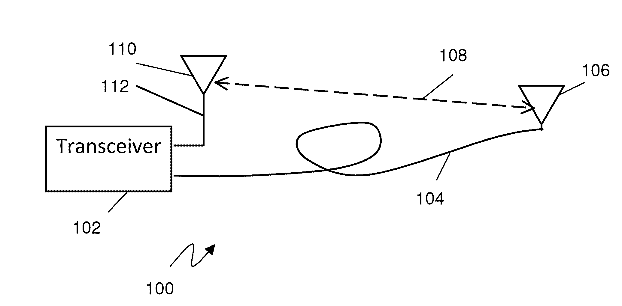
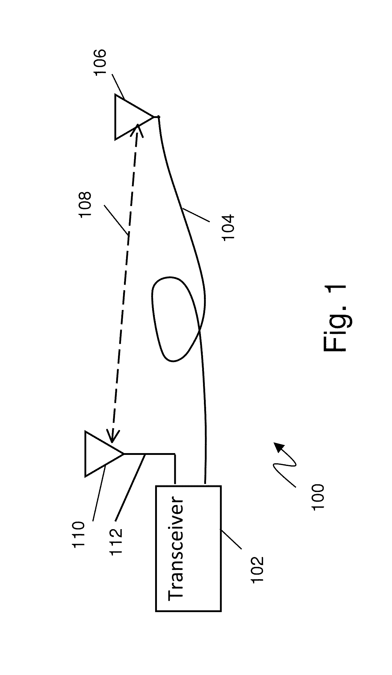
[0156]FIG. 1 is an exemplary block diagram of a distance measuring system in accordance with the present disclosure. Referring to FIG. 1, a transceiver 102 is coupled to a first antenna 106 and a second antenna 110 for measuring distance 108 between the two antennas 106, 110. Antenna 106 may typically be a movable or mobile antenna connected to the transceiver through relatively long cable 104, whereas antenna 110 may typically be connected to the receiver through optional cable 112. Antenna 106 may preferably be connected to the transmit portion of transceiver 102. By connecting the longer cable to the transmit side allows the transmit power to be increased to overcome cable loss while maintaining specified transmit field strength at the antenna. In addition this configuration allows the transmit antenna to be placed inside the device under test promoting increased transmit power while maintaining specified transmit field strength at the surface of the device under test.

[0157]More ...


PUM


Abstract

Determination of distance and / or position relative to one or more points by transmission of a wideband signal by a first antenna, reception of the transmitted wideband signal by a second antenna and comparison of the time delay between the transmitted and received signals. The first and second antennas are connected to a timer / processor unit. One or more of the first or second antennas is movable to an unknown position to be measured, but maintains connection to the timer / processor through a fixed or known delay communication link. The timer / processor contains a time base for generating the transmitted signal and an offset timer for measuring the time delay of the received signal. The received signal may be processed to determine a start time or leading edge that may resolve RF cycle and modulation bandwidth ambiguities and may allow positive determination of distance much shorter than a wavelength at the operation center frequency.

Description

RELATED APPLICATIONS[0001]This application claims the benefit under 35 USC 119(e) of U.S. provisional application 61 / 847,963 titled “One Way Time of Flight Distance Measurement”, filed Sep. 6, 2013 by Dewberry et al., which is incorporated herein by reference in its entirety; this application is a continuation in part of application Ser. No. 13 / 872,030 titled “High Capacity Ranging Using Direct-path Signal Strength”, filed Apr. 26, 2013 by Dewberry et al which is a non-provisional application of provisional application 61 / 639,056, titled: “High Capacity Ranging Network Using Ultra-Wideband Direct-path Pulse Signal Strength with Dynamic Recalibration”, filed Apr. 26, 2012 by Dewberry; Ser. No. 13 / 872,030 is also a continuation in part of application Ser. No. 13 / 745,700 titled “Distance Measuring Quality Factor Using Signal Characterization”, filed Jan. 18, 2013 by Dewberry et al., which is a nonprovisional of provisional application 61 / 587,912 titled “Distance Measuring Error Varianc...

Claims


Application Information

Patent Timeline
Patent Type & Authority Applications(United States)
IPC IPC(8): G01S13/00
CPCG01S13/003G01S11/02G01S11/08
Inventor DEWBERRY, BRANDON SCOTTPEDERSON, GERT FROLUNDEGGERS, PATRICK CLAUS FRIEDRICH
Owner HUMATICS CORP
Why Eureka
Try Eureka