Methods for Updating 2D/3D Registration on Movement and Computing Device

a computing device and 2d/3d technology, applied in image data processing, diagnostics, sensors, etc., can solve the problems of no simple solution for tracking patient movement in projection images, loss of depth information in projection images, and distraction of doctors from performing the process, so as to facilitate observation of contours

Active Publication Date: 2015-01-29
SIEMENS HEALTHCARE GMBH
View PDF5 Cites 22 Cited by
  • Summary
  • Abstract
  • Description
  • Claims
  • Application Information

AI Technical Summary

Benefits of technology

[0017]Rigid objects in target areas (e.g., inside a patient undergoing treatment and / or diagnosis) may be observed. In some embodiments, the rigid object may correspond to an anatomical feature (e.g., at least a bone, such as a skull). In other embodiments, the rigid object may correspond to a medical instrument introduced into the patient (e.g., a stent or a marker device). Many target areas and tasks (e.g., imaging in the region of the skull) may facilitate observation of the contours occurring in the image (e.g., pronounced differences in contrast or image value) since the entire target area may be perceived as a conjointly moving, rigid object. In accordance with the present teachings, instead of using landmarks (e.g., a tip of a catheter), any rigid part of the body may be used (e.g., bones that are clearly visible as the most likely expected rigid structure in an X-ray projection image, such as bone structures surrounded by an aqueous environment). To minimize confusion with introduced instruments and the like, a segmentation may be performed in the three-dimensional image data set (e.g., separately according to different tissue types and the like).

Problems solved by technology

However, there are a number of causes that may result in inaccuracies during the procedure (e.g., at least the period of time wherein projection images are captured).
However, the physician may be distracted from performing the process by the movement correction.
However, there is no simple solution for tracking patient movement in projection images.
Thus, the depth information is lost in the projection image.
As a result, derivation of the three-dimensional movement from X-ray projection image sequences by tracking algorithms is difficult.
However, conventional methods are not sufficiently fast to permit real-time tracking of the movement and, therefore, real-time compensation for the movement.
However, in this approach, normal tracking algorithms are not suitable for X-ray projection images.

Method used


Image

  • Methods for Updating 2D/3D Registration on Movement and Computing Device
  • Methods for Updating 2D/3D Registration on Movement and Computing Device
  • Methods for Updating 2D/3D Registration on Movement and Computing Device

Examples


Embodiment Construction

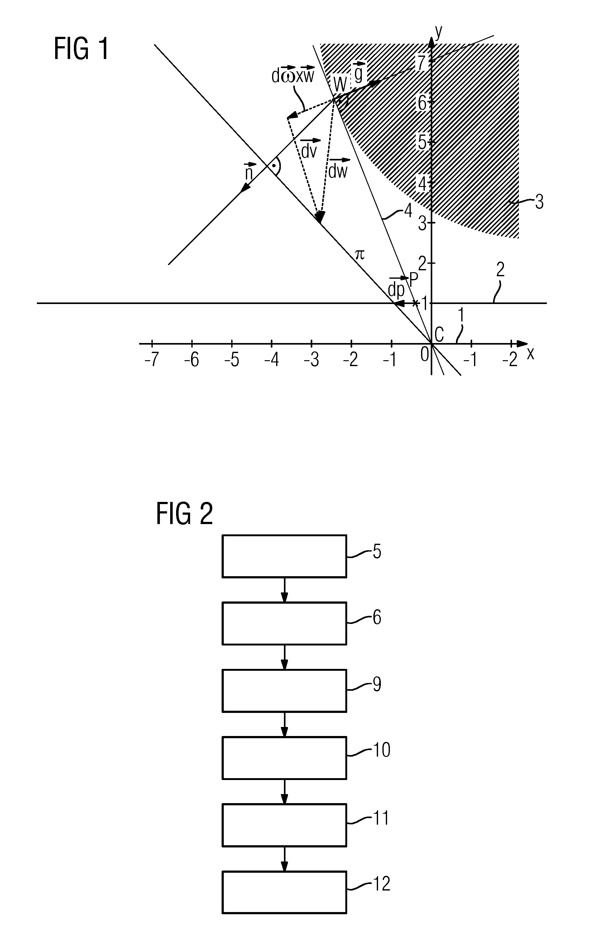
[0046]FIG. 1 shows an example of geometrical considerations that underlie methods in accordance with the present teachings, and explains the derivation and notations used herein. An x-y plane of a coordinate system 1 is shown wherein both the position of the three-dimensional image data set and the position of at least the first projection image are known (e.g., based on the 2D / 3D registration known for the first projection image). The above-described gradient vector g lies in the plane in FIG. 1. Points are represented by uppercase letters (e.g., the contour points W, P in the three-dimensional image data set or in the two-dimensional projection image). Vectors are shown by boldfaced lowercase letters. The vectors may be assumed to be column vectors, such that the scalar product between two vectors a and b results in aTb.

[0047]As shown in FIG. 1, the origin of the coordinate system 1 is chosen as the focal point C of the X-ray radiation source and used as the projection center. The...


PUM


Abstract

Methods for updating a 2D/3D registration between a three-dimensional image data set corresponding to a target area subjected to a movement and a plurality of two-dimensional projection images of the target area include: selecting a plurality of contour points along a contour, the contour being visible in a first projection image and a three-dimensional image data set registered therewith, the plurality of contour points being associated with a rigid object in the target area; determining a displacement of each contour point of the plurality of contour points between the first projection image and a successively captured second projection image; obtaining movement information for each contour point of the plurality of contour points based on the determined displacement, the movement information describing a movement of the rigid object; and updating the registration based on the obtained movement information.

Description

RELATED APPLICATIONS[0001]This application claims the benefit of German Patent Application No. DE 102013214479.2, filed Jul. 24, 2013. The entire contents of the priority document are hereby incorporated herein by reference.TECHNICAL FIELD[0002]The present teachings relate generally to methods for updating a 2D / 3D registration between an initially captured three-dimensional image data set of a target area subjected to a movement that relates to the updating and a plurality of two-dimensional projection images of the target area captured during a process (e.g., a treatment process). In some embodiments, the present teachings further relate to computing devices for executing the methods.BACKGROUND[0003]2D / 3D image fusion may be employed on a patient for radiological monitoring of interventions (e.g., treatment processes). For example, three-dimensional image data sets (e.g., CT image data sets and / or magnetic resonance image data sets) captured prior to the intervention are superimpos...

Claims


Application Information

Patent Timeline
Patent Type & Authority Applications(United States)
IPC IPC(8): A61B6/00G06T7/00A61F2/82A61B6/12A61B19/00
CPCA61B6/5241A61B6/12A61B6/505A61B19/54G06T2207/30008A61B6/501G06T7/0028A61B2019/5466G06T2207/10124A61F2/82A61B6/032A61B6/487A61B2090/364A61B2090/367G06T7/246G06T7/33G06T2207/10072G06T2207/10121G06T2207/30004
Inventor BORSDORF, ANJAHEIGL, BENNOWANG, JIAN
Owner SIEMENS HEALTHCARE GMBH
Why Eureka
Try Eureka