Excimer lamp

a mercury lamp and excimer technology, applied in the field of excimer lamps, can solve the problems of large influence on the light-emission characteristics of low-pressure mercury lamps, insufficient light emission, corrosion of external electrodes, etc., and achieves long service life, high safety, and large capacitance

Active Publication Date: 2015-02-05
USHIO DENKI KK
View PDF7 Cites 6 Cited by
  • Summary
  • Abstract
  • Description
  • Claims
  • Application Information

AI Technical Summary

Benefits of technology

[0053]In the first excimer lamp of the present invention, one of the electrodes is disposed inside the light-emitting tube, and the other electrode is disposed in the tube wall of the light-emitting tube. Therefore, dielectric barrier discharge can be generated between the pair of electrodes, so radiation light can be obtained by utilizing the dielectric barrier discharge. Since any of the pair of electrodes are not exposed to the outside of the light-emitting tube, the electrodes do not come into contact with gas, liquid, etc. that is present outside the light-emitting tube according to the use environment, so no harmful effects occur which are caused when the electrodes are exposed to the outside of the light-emitting tube. Since the one electrode and the other electrode face each other in a reliable manner irrespective of the embedded position of the other electrode in the tube wall of the light-emitting tube, stable discharge is obtained in the inner space of the light-emitting tube.
[0054]A hermetically sealed portion having a foil seal structure in which a conductive foil electrically connected to the one electrode is embedded is formed in an end portion of the light-emitting tube. In this configuration, the one electrode and the light-emitting tube are not in direct contact with each other in the hermetically sealed portion. Therefore, when the lamp emits light, although thermal expansion occurs in the one electrode and the conductive foil, the thermal expansion in the one electrode and the conductive foil can be absorbed by plastic deformation of the conductive foil and thereby relaxed. Therefore, the occurrence of breakage of the hermetically sealed portion due to the difference in thermal expansion coefficient between the material of the electrodes, the material of the conductive foil and the material of the light-emitting tube can be suppressed.
[0055]In the first excimer lamp of the present invention, no corrosion occurs in the electrodes in any use environment, and high safety can thereby be obtained. In addition, since the occurrence of breakage of the end portion of the light-emitting tube in which the hermetic seal structure is formed is suppressed, long service life is obtained.
[0056]In the second excimer lamp of the present invention, one of the electrodes is disposed in the hermetic space inside the cylindrical tube made of a dielectric material so as to be in contact with the inner surface of the tube wall of the cylindrical tube, and the other electrode is disposed so as to face the one electrode through the tube wall of the cylindrical tube and the light-emitting space. Therefore, dielectric barrier discharge can be generated between the pair of electrodes, so radiation light can be obtained by utilizing the dielectric barrier discharge. Since the pair of electrodes are disposed inside the light-emitting tube and are not exposed to the outside of the light-emitting tube, the electrodes do not come into contact with gas, liquid, etc. that is present outside the light-emitting tube according to the use environment, so no harmful effects occur which are caused when the electrodes are exposed to the outside of the light-emitting tube.
[0057]Hermetically sealed portions having foil seal structures in which conductive foils electrically connected to the respective ones of the pair of electrodes are embedded are formed in the end portions of the light-emitting tube. In this configuration, the electrodes and the light-emitting tube are not in direct contact with each other in the hermetically sealed portions. Therefore, when the lamp emits light, although thermal expansion occurs in the electrodes and the conductive foils, the thermal expansion in the electrodes and the conductive foils can be absorbed by plastic deformation of the conductive foils and thereby relaxed. The occurrence of breakage of the hermetically sealed portions due to the difference in thermal expansion coefficient between the material of the electrodes, the material of the conductive foils and the material of the light-emitting tube can thereby be suppressed. Since the cylindrical tube disposed with the one electrode in contact therewith can have a large capacitance, the pair of electrodes can be supplied with large electric power, and the light-emitting space can thereby be supplied with larger electric power. Moreover, since each of the hermetically sealed portions at the ends of the light-emitting tube has a foil seal structure, these hermetically sealed portions can be easily formed by pinch sealing or shrink sealing.
[0058]Therefore, according to the second excimer lamp of the present invention, the light-emitting space can be supplied with large electric power. In addition, the occurrence of breakage of each end portion of the light-emitting tube having the hermetic seal structure formed therein is suppressed, and long service life can thereby be obtained. Moreover, the second excimer lamp can be easily produced.

Problems solved by technology

A problem that occurs under such use conditions is that the light-emission characteristics of the low-pressure mercury lamp are greatly affected by the temperature of water.
When the temperature of water is extremely low, mercury is not sufficiently vaporized, and this causes a problem in that sufficient light emission is not obtained.
However, in this external electrode discharge lamp, the electrodes to which high voltage is applied are located outside and exposed, and this causes various problems depending on use environment conditions.
Specifically, when an external electrode discharge lamp is used as the light source of a water treatment apparatus and disposed in water to be treated, the external electrodes come into contact with water, so corrosion may occur in the external electrodes.
Corrosion of the external electrodes causes not only a problem in that the external electrodes themselves wear and therefore adversely affect discharge but also a problem in that corrosion products falling from the surfaces of the corroded external electrodes are mixed into the water to be treated.
Another problem is that since the external electrodes are exposed to the outside of the light-emitting tube, an electric leakage or an electric shock may occur, so that sufficient safety cannot be obtained.
These problems not only occur when the external electrode discharge lamp is used as the light source of a water treatment apparatus but also occur similarly when the external electrode discharge lamp is used as the light source of, for example, an air sterilization apparatus because water vapor is present in air.
However, when air is present inside the wrapper tube, micro discharge may occur in the gaps between the light-emitting tube and the external electrodes, and therefore ozone may be generated.
This causes a problem in that harmful effects such as corrosion of the electrodes occur.
However, this excimer lamp has a problem in that, particularly when glass is used as the dielectric material and the dielectric layer is interposed between the light-emitting tube and the metal rod constituting the electrode at a seal portion of the light-emitting tube, the light-emitting tube may break at the seal portion because of the difference in thermal expansion coefficient between the material of the metal rod and the dielectric material.
This problem also occurs in a seal portion of the light-emitting tube when the light-emitting tube and a metal rod constituting an electrode are in direct contact with each other and the light-emitting tube is made of the same material as the dielectric material (the material constituting the dielectric layer).
This excimer lamp has a problem in that, when the electrodes (metal rods) are spaced apart from the inner surfaces of the inner tubes, the capacitance of the inner tubes becomes small.
However, the following problems occur in these cases.
Therefore, particularly when glass is used as the dielectric material constituting the inner tubes, a problem occurs in that the seal portions may break because of the difference in thermal expansion coefficient between the material of the metal rods and material of the inner tubes (the dielectric material).

Method used


Image

  • Excimer lamp
  • Excimer lamp
  • Excimer lamp

Examples


experimental example 1

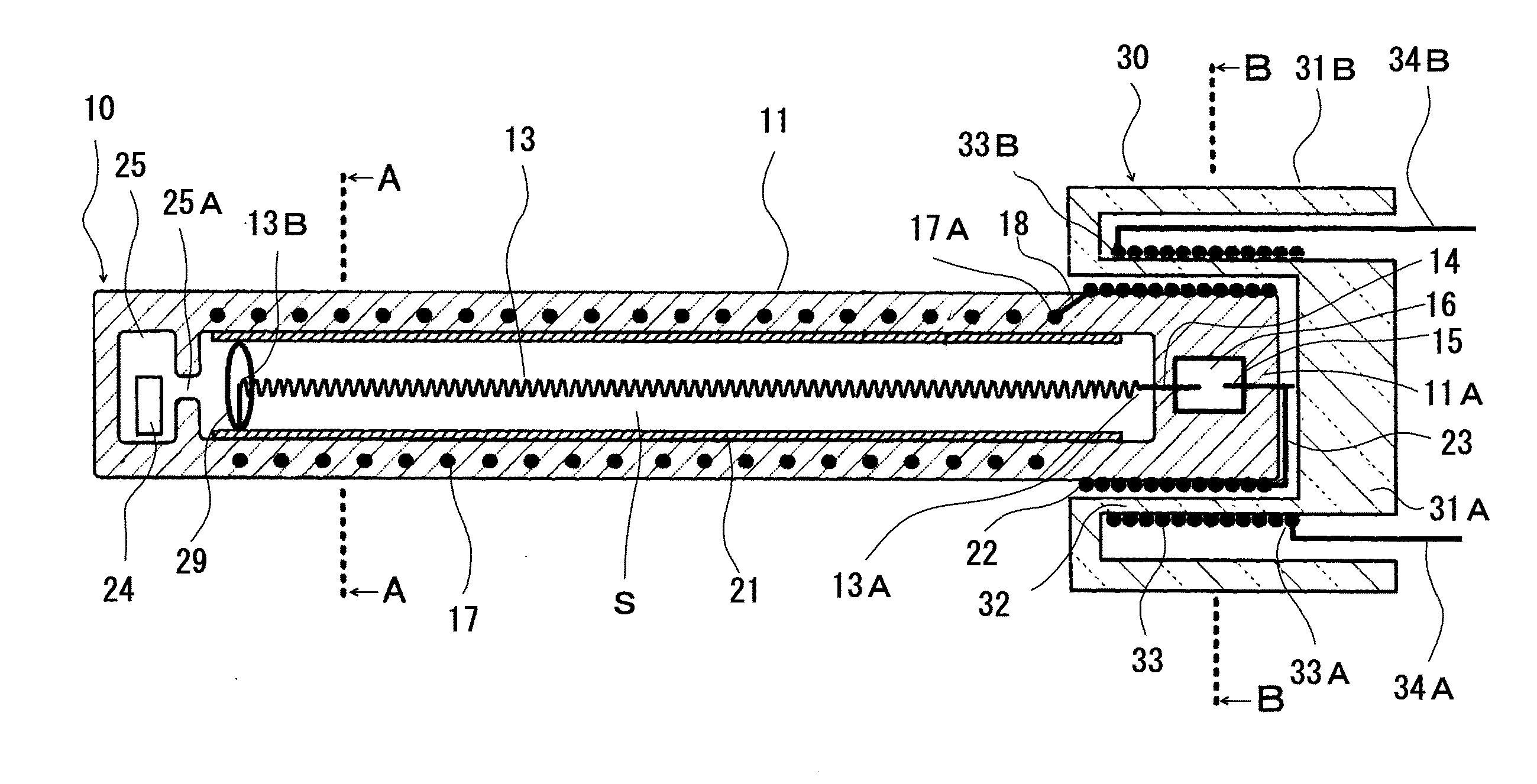
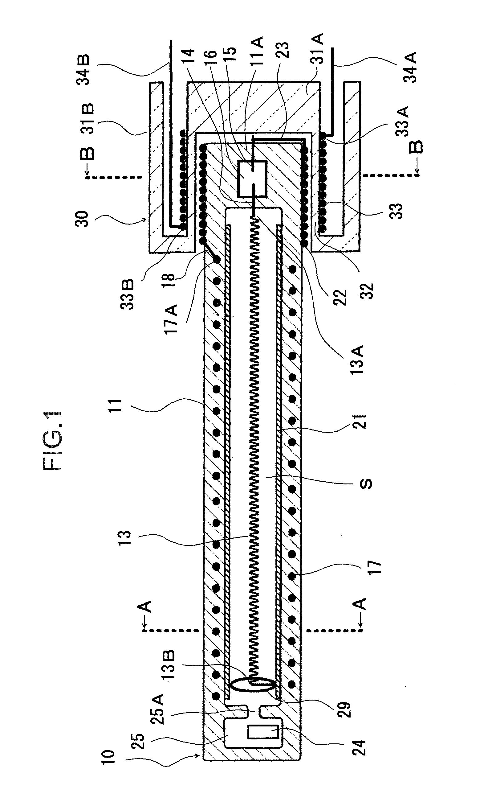
[0317]First, a third excimer lamp having the configuration in FIG. 14 (this third excimer lamp may hereinafter be referred to as an “excimer lamp (1)”) was produced.

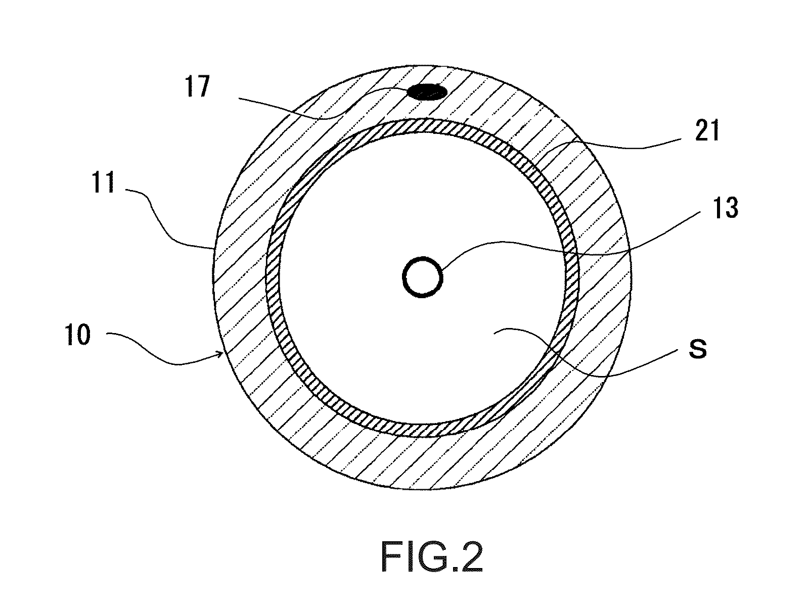
[0318]In the produced excimer lamp (1), the light-emitting tube 91 had an outer diameter of 18 mm, an inner diameter of 16 mm and an overall length of 200 mm, and the cylindrical tube 92 had an outer diameter of 4 mm, an inner diameter of 2 mm and an overall length of 170 mm. The conductive foils 93A and 93B were each a molybdenum foil.

[0319]The coil-shaped electrode constituting the first electrode 96 was formed from a tungsten wire having a wire diameter of 0.36 mm and had an outer diameter (coil outer diameter) of 2 mm, a coil pitch of 4.7 mm and an overall length of 150 mm.

[0320]The coil-shaped electrode constituting the second electrode 97 was formed from a tungsten wire having a wire diameter of 0.36 mm and included: a large-diameter portion 97A having an inner diameter (coil inner diameter) of 14 mm, a coil pitch ...


PUM


Abstract

A first excimer lamp includes: a quartz glass-made light-emitting tube containing an excimer emission gas sealed therein; and a pair of electrodes for generating dielectric barrier discharge. One of the pair of electrodes is disposed in the inner space of the light-emitting tube so as to extend in the direction of a tube axis of the light-emitting tube, and the other one of the pair of electrodes is embedded in the tube wall of the light-emitting tube so as to extend in the direction of the tube axis of the light-emitting tube. The one electrode is electrically connected to a conductive foil hermetically embedded in an end portion of the light-emitting tube.

Description

TECHNICAL FIELD[0001]The present invention relates to an excimer lamp.BACKGROUND ART[0002]Low-pressure mercury lamps have been widely used as light sources of water treatment apparatuses for, for example, performing so-called sterilization to decompose organic materials contained in water or to kill germs contained in water (see, for example, Patent Literatures 1 and 2).[0003]However, when a low-pressure mercury lamp is used as the light source of a water treatment apparatus, the low-pressure mercury lamp is often placed in water to be treated. A problem that occurs under such use conditions is that the light-emission characteristics of the low-pressure mercury lamp are greatly affected by the temperature of water.[0004]The reason that such a problem occurs is that the low-pressure mercury lamp contains mercury as a light-emitting material and the vapor pressure of mercury must reach a prescribed level during operation in order to obtain a favorable light-emitting state. When the te...

Claims


Application Information

Patent Timeline
Patent Type & Authority Applications(United States)
IPC IPC(8): H01J61/06H01J61/42
CPCH01J61/42H01J61/06C02F1/325H01J5/54H01J61/34H01J61/92H01J65/04H01J65/046C02F2201/3223H01J7/183H01J61/26H01J61/44C09K11/7777C09K11/778
Inventor HISHINUMA, NOBUYUKITAGAWA, YUKIHARUASAYAMA, JUNYATAKEGOSHI, KOICHIYAMADA, KOSUKE
Owner USHIO DENKI KK
Why Eureka
Try Eureka