
Method and device for determination of a magnetic resonance control sequence

a magnetic resonance control and sequence technology, applied in the direction of reradiation, measurement using nmr, instruments, etc., can solve the problem of not achieving sufficient spatial localization with such a “ puls

Active Publication Date: 2015-02-05
SIEMENS HEALTHCARE GMBH
View PDF5 Cites 17 Cited by
  • Summary
  • Abstract
  • Description
  • Claims
  • Application Information

AI Technical Summary

Benefits of technology

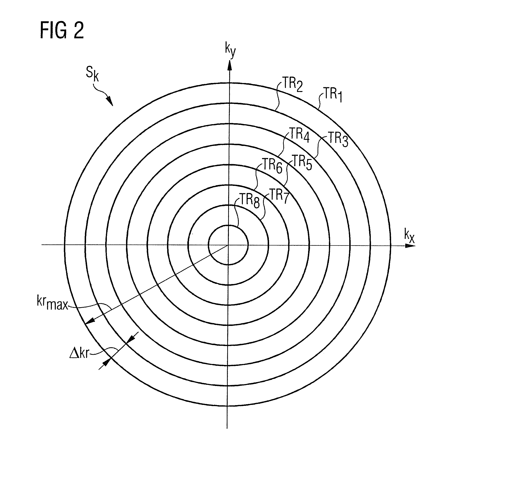
The present invention provides a method and device for determining a magnetic resonance control sequence that avoids problems caused by gradient delay times in two-dimensional selective excitation of a rotationally-symmetrical excitation profile. The invention also includes designing partial RF pulses and gradient pulses with individualized duration to optimize the sequence and minimize the total duration of RF excitation pulse while complying with boundary conditions. Additionally, the invention suggests using pre-phasing and rephasing gradients before and after individual partial RF pulses to save time. The invention also proposes designing concentric circular k-space transmission trajectories with different radial spacing to ensure sufficient energy deposition in the important frequency ranges and save time in the less important edge regions of k-space.

Problems solved by technology

However, a sufficient spatial localization is not achieved with such a “π pulse”.

Method used


Image

  • Method and device for determination of a magnetic resonance control sequence
  • Method and device for determination of a magnetic resonance control sequence
  • Method and device for determination of a magnetic resonance control sequence

Examples


Embodiment Construction

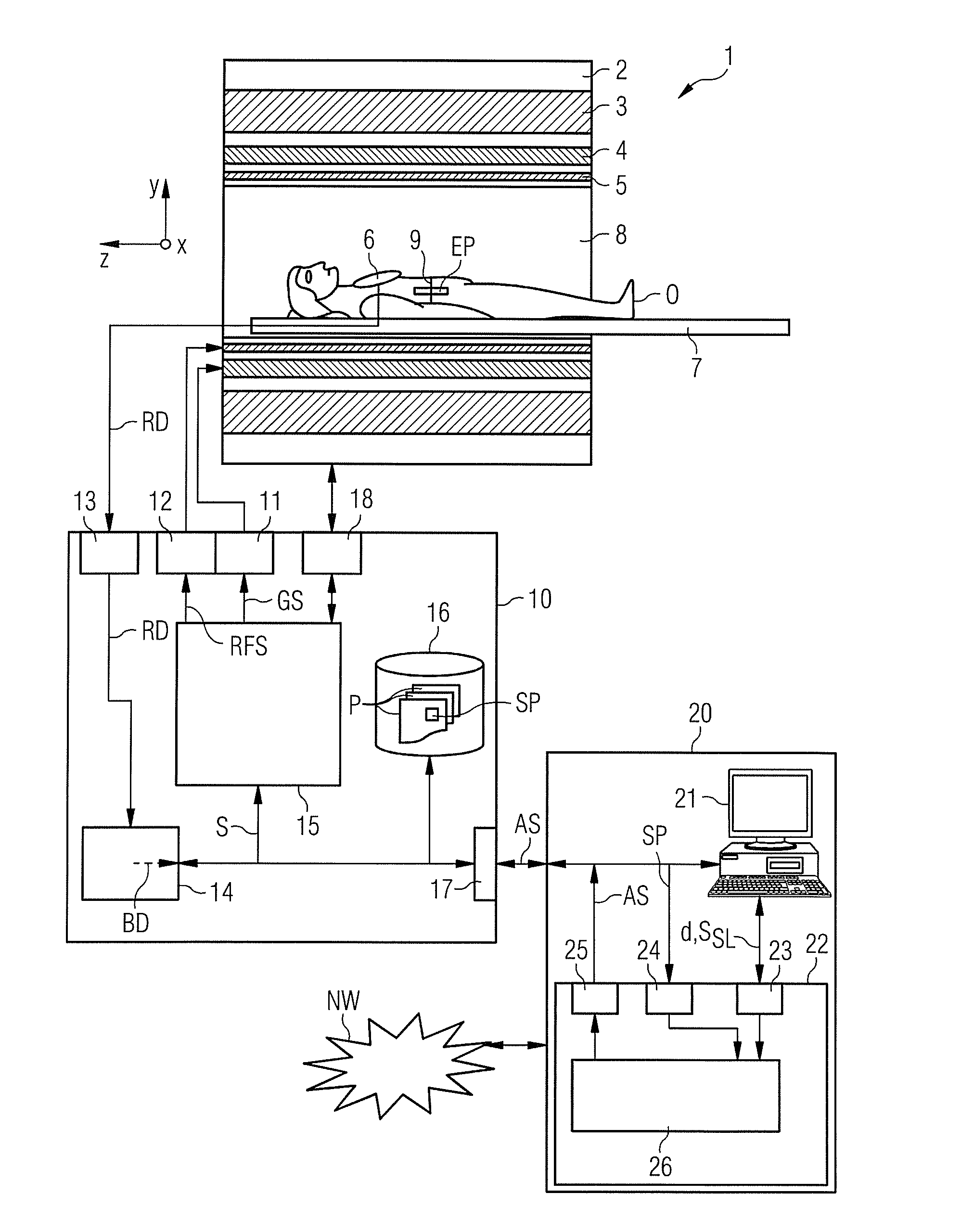
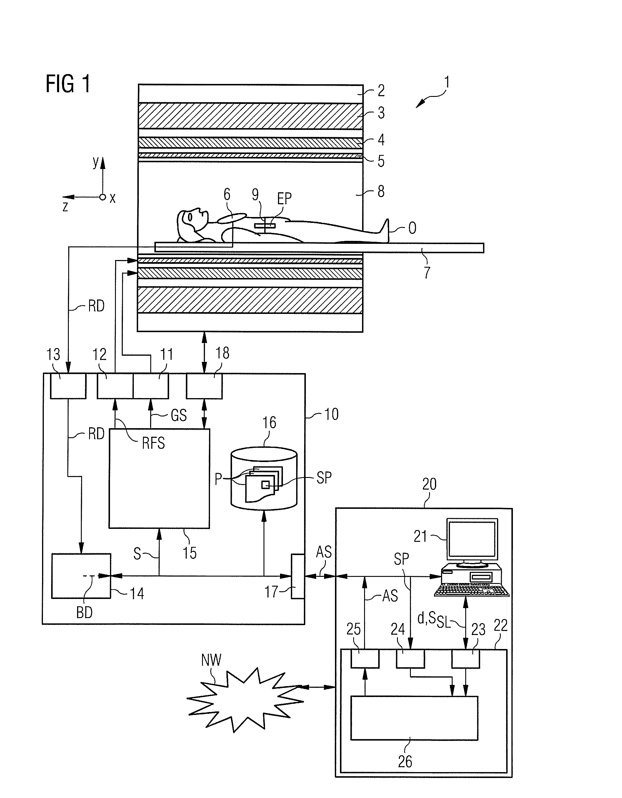
[0055]A magnetic resonance (MR) system 1 according to the invention is schematically depicted in FIG. 1. The system includes the actual magnetic resonance scanner 2 with an examination space 8 or patient tunnel located therein. A bed 7 can be driven into this patient tunnel 8, such that a patient O or test subject lying on the bed 7 can be supported at a defined position within the magnetic resonance scanner 2 (relative to the magnet system and radio-frequency system arranged therein) during an examination. The patient O or test subject on the bed 7 also can be moved between different positions during a measurement (data acquisition).

[0056]Among the components of the magnetic resonance scanner 2 are a basic field magnet 3, a gradient system 4 with magnetic field gradient coils to generate magnetic field gradients in the x-, y- and z-direction, and a whole-body radio-frequency (RF) coil 5. The magnetic field gradient coils in the x-, y- and z-direction are controllable independently ...


PUM


Abstract

A magnetic resonance control sequence with a pulse arrangement that acts selectively in at least two spatial directions in order to excite a limited rotationally symmetrical excitation profile within an examination subject has an RF excitation pulse formed as a sequence of multiple partial RF pulses, and gradient pulses in the two spatial directions that are coordinated with the partial RF pulses so that the RF energy introduction of different partial RF pulses in transmission k-space occurs on circular k-space transmission trajectories that are concentric to one another. The amplitude of the RF envelope of the partial RF pulses is constant during the duration of a traversal of each circular k-space trajectory. The control sequence can also be used in a calibration of a magnetic resonance system.

Description

BACKGROUND OF THE INVENTION[0001]1. Field of the Invention[0002]The invention concerns a method to determine a magnetic resonance control sequence with a pulse arrangement that acts selectively in at least two spatial directions in order to excite a limited, rotationally symmetrical excitation profile within an examination subject. Moreover, the invention concerns a method to operate a magnetic resonance system with such a magnetic resonance control sequence; a method to calibrate a magnetic resonance system using such a method; a control sequence determination device in order to determine such a magnetic resonance control sequence; and a magnetic resonance system with such a control sequence determination device.[0003]2. Description of the Prior Art[0004]In a magnetic resonance tomography system (also called a magnetic resonance system), the body to be examined is typically exposed to a relatively high, optimally homogeneous basic magnetic field (B0 field)—for example of 1, 5, 3 or...

Claims


Application Information

Patent Timeline
Patent Type & Authority Applications(United States)
IPC IPC(8): G01R33/483G01R33/565G01R33/54G01R35/00
CPCG01R33/4836G01R33/543G01R33/56572G01R35/005G01R33/4824
Inventor STEMMER, ALTO
Owner SIEMENS HEALTHCARE GMBH
Learn More