Projection apparatus

a projection device and projection technology, applied in the field of projection devices, can solve the problems of reducing affecting the efficiency of light utilization, so as to improve the efficiency of utilization of rgb laser lights, eliminate any positional displacement

Active Publication Date: 2015-02-05
CITIZEN WATCH CO LTD
View PDF16 Cites 43 Cited by
  • Summary
  • Abstract
  • Description
  • Claims
  • Application Information

AI Technical Summary

Benefits of technology

[0033]The above projection apparatus can enhance the efficiency of utilization of RGB laser lights while eliminating any positional displacement in projection point occurring due to the spaced-apart arrangement of the fiber cores for emitting the respective laser lights, and can detect additional information such as image distortion or depth information while projecting an image with the RGB laser lights.

Problems solved by technology

However, with the fused fiber method, it is generally difficult to control the coupling length with high accuracy.
As a result, unintended crosstalk, etc., may occur between the adjacent cores, causing leakage of the light to be combined at the output and thus reducing the efficiency of light utilization.
On the other hand, in the case where a fiber bundle is used rather than a fused fiber combiner, if the fibers are simply bundled using a ferrule, the projected image will appear blurred.
Further, if the scanning unit for scanning the RGB laser lights in a two-dimensional manner is constructed, for example, from a resonant MEMS (Micro Electro Mechanical System) scanner, the projected image may be distorted as the resonant frequency varies due to variations in the temperature of the MEMS scanner.
However, if the correction is to be made using visible RGB lights, it is not possible to measure the image distortion while at the same time projecting the image to be displayed, and thus it is difficult to correct distortion of the projected image in real time.
The depth information can be detected using visible light, but if visible light is used, there arises a problem in that the depth information cannot be detected unless an image is projected.
On the other hand, if infrared light is used to detect the depth information, it is difficult to reduce the size and cost of the apparatus, because a depth sensor usually has to be provided separately from the projection apparatus.

Method used


Image

  • Projection apparatus
  • Projection apparatus
  • Projection apparatus

Examples


Embodiment Construction

[0049]Hereinafter, with reference to the drawings, a projection apparatus will be explained in detail. However, it should be noted that the technical scope of the present invention is not limited to embodiments thereof, and includes the invention described in claims and equivalents thereof.

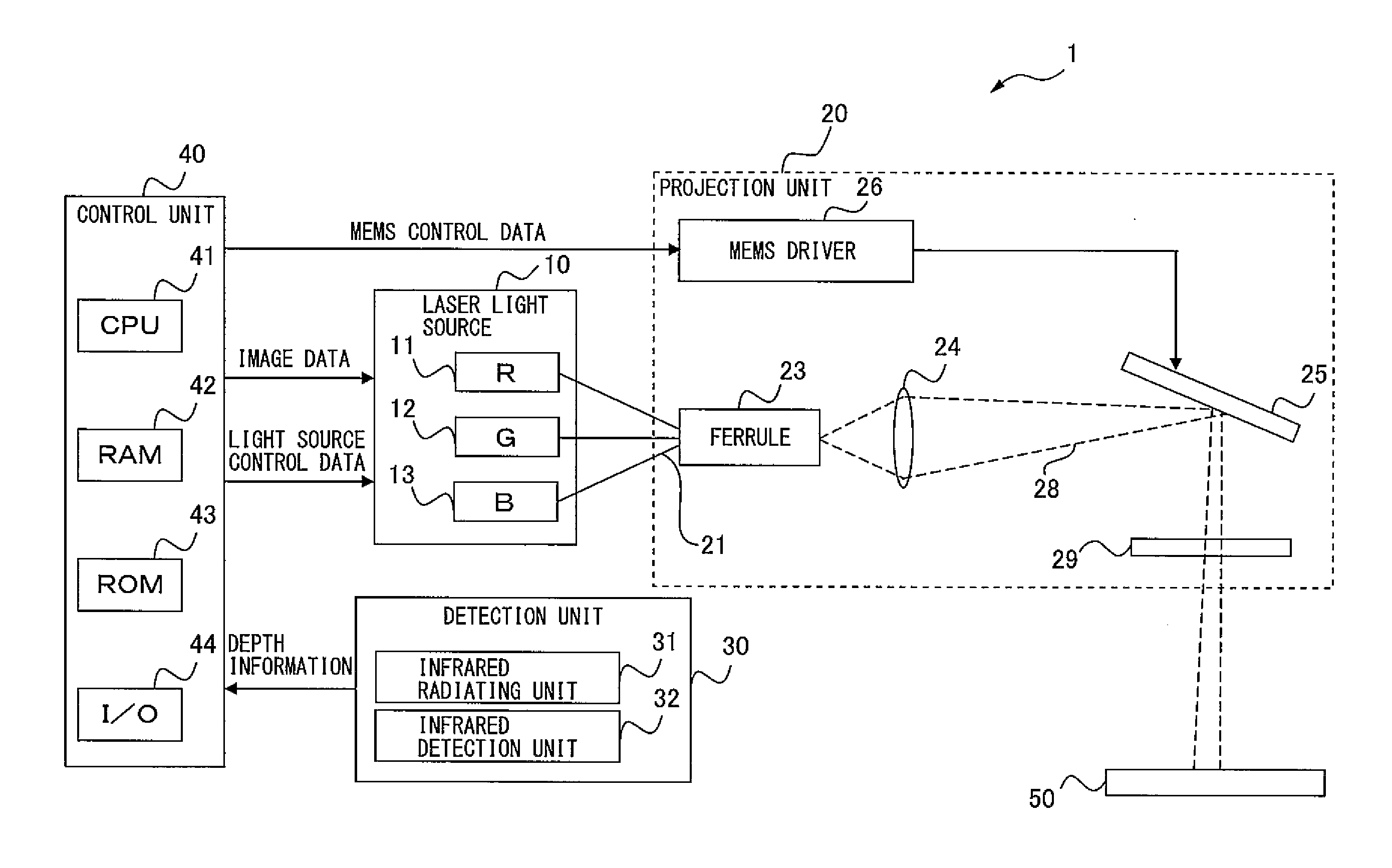
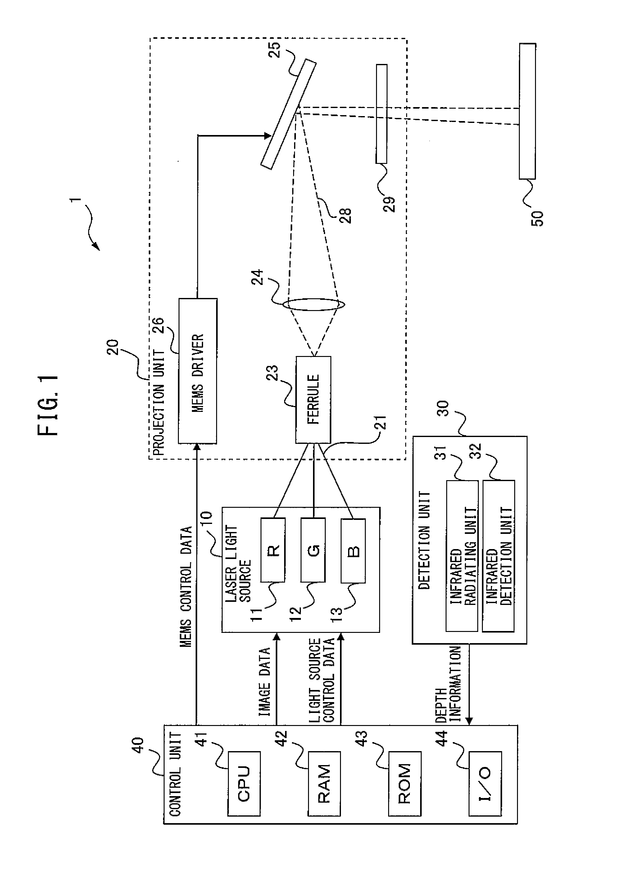
[0050]FIG. 1 is a diagram for explaining the general configuration of a laser projector 1. The laser projector 1 is one example of the projection apparatus, and includes a laser light source 10, a projection unit 20, a detection unit 30, and a control unit 40 as major component elements. The laser projector 1 outputs, from three fibers bundled together by a ferrule, laser lights of different colors emitted from the laser light source 10, and projects an image onto a projection surface 50 by scanning the output lights in a two-dimensional manner via a MEMS (Micro Electro Mechanical System) scanner moving in a swinging fashion.

[0051]The laser light source 10 includes laser diodes (LDs) 11, 12, and 1...


PUM


Abstract

Provided is a projection apparatus that can enhance the efficiency of utilization of RGB laser lights, eliminate positional displacement in projection point caused by spaced-apart fiber cores emitting the laser lights, and detect additional information while projecting an image with the laser lights. The projection apparatus includes a laser light source emitting infrared and RGB laser lights, a fixing device fixing end portions of an infrared-light fiber and colored-light fibers used to transmit the infrared and RGB laser lights, a scanning unit projecting an image on a projection surface by scanning the projection surface with the RGB laser lights emitted from the end portions of the colored-light fibers, a detection unit detecting reflection of the infrared laser light emitted from the end portion of the infrared-light fiber, and a control unit controlling emission of the RGB laser lights from the light source, based on information detected by the detection unit.

Description

TECHNICAL FIELD[0001]The present invention relates to a projection apparatus for projecting an image on a projecting surface by scanning laser light across the surface.BACKGROUND ART[0002]It is known to provide a laser projector that produces any desired color by combining, using a fused fiber combiner, the pigtails of fibers used to transmit laser lights of three primary colors red (R), green (G), and blue (B), respectively. It is also known to provide a light source apparatus that does not use such a fused fiber combiner but uses a fiber bundle fastened and fixed together by means of a ferrule.[0003]Patent document 1 discloses a light source apparatus that includes a plurality of core / clad type optical fibers which are brought closer to each other and bundled together in parallel fashion by reducing the outer clad diameter of each optical fiber toward one end thereof while retaining its core diameter, and an optical unit which optically couples the other end of each of the optical...

Claims


Application Information

Patent Timeline
Patent Type & Authority Applications(United States)
IPC IPC(8): H04N9/31G01S17/89
CPCH04N9/3185G02B6/065H04N9/3138H04N9/3129H04N3/08G01S17/08G01S17/46G01S17/89H04N9/317H04N9/3132H04N9/3135H04N3/22
Inventor IDE, MASAFUMIFUKAYA, SHINPEISUZUKI, MASAYA
Owner CITIZEN WATCH CO LTD
Why Eureka
Try Eureka